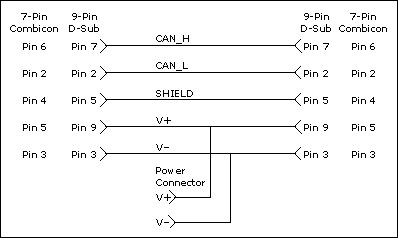
Low-Speed/Fault-Tolerant CAN Pinout Cable
Low-Speed/Fault-Tolerant PCI, PXI, and USB Connector Pinout
PCI-CAN/LS, PXI-8460, USB-8472, and USB-8472s hardware have a 9-pin male D-SUB (DB9) connector for each port. The 9-pin D-SUB connector follows the pinout recommended by CiA DS 102. The following figure shows the 9-pin D-SUB connector pinout.
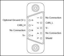
Pinout for 9-Pin D-SUB Connector
| 9-Pin D-SUB Connector Pin Descriptions | ||
|---|---|---|
| D-SUB Pin | Signal | Description |
| 1 | No Connection | — |
| 2 | CAN_L | CAN_L bus line |
| 3 | V- | CAN reference ground |
| 4 | No Connection | — |
| 5 | (Shield) | Optional CAN shield |
| 6 | (V-) | Optional CAN reference ground |
| 7 | CAN_H | CAN_H bus line |
| 8 | No Connection | — |
| 9 | (V+) | Optional CAN power supply if bus power or external VBAT is required |
CAN_H and CAN_L are signals lines that carry the data on the CAN network. These signals should be connected using twisted-pair cable.
V- serves as the reference ground for CAN_H and CAN_L.
V+ supplies bus power to the CAN physical layer if external power is required. All Low-Speed/Fault-Tolerant Series 2 PCI, PXI and USB hardware is powered internally, so it is not necessary to supply V+ unless you have configured the VBAT jumper for EXT.
Shield is an optional connection when using a shielded CAN cable. Connecting the optional CAN shield may improve signal integrity in a noisy environment.
PCMCIA Connector Pinout PCMCIA Connector Pinout
PCMCIA-CAN cables have both a 9-pin male D-SUB and Combicon-style pluggable screw terminal connector for each port. The following figure shows the end of a PCMCIA-CAN cable. The arrow points to pin 1 of the 7-pin screw terminal block. All of the signals on the 7-pin screw terminal, except RTL and RTH, are connected directly to the corresponding pins on the 9-pin D-SUB.
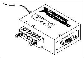
PCMCIA-CAN/LS Cable
| PCMCIA-CAN/LS Cable Connector Pin Descriptions | |||
|---|---|---|---|
| D-SUB Pin | Combicon Pin | Signal | Description |
| 1 | — | No Connection | — |
| 2 | 2 | CAN_L | CAN_L bus line |
| 3 | 3 | V- | CAN reference ground |
| 4 | — | No Connection | — |
| 5 | 4 | (Shield) | Optional CAN shield |
| 6 | — | (V-) | Optional CAN reference ground |
| 7 | 6 | CAN_H | CAN_H bus line |
| 8 | — | No Connection | — |
| 9 | 5 | No Connection | — |
CAN_H and CAN_L are signal lines that carry the data on the CAN network. These signals should be connected using twisted-pair cable.
V- serves as the reference ground for CAN_H and CAN_L.
Shield is an optional connection when using a shielded CAN cable. Connecting the optional CAN shield may improve signal integrity in a noisy environment.
Cabling Requirements for Low-Speed/Fault-Tolerant CAN
Cables should meet the physical medium requirements shown in the following table.
| Specifications for Characteristics of a CAN_H and CAN_L Pair of Wires | |
|---|---|
| Characteristic | Value |
| Length-related resistance | 90 m /m nominal
 |
| Length-related capacitance: CAN_L and ground, CAN_H and ground, CAN_L and CAN_H | 30 pF/m nominal |
Belden cable (3084A) meets all of those requirements, and should be suitable for most applications.
Number of Devices
The maximum number of devices depends on the electrical characteristics of the devices on the network. If all of the devices meet the requirements of typical Low-Speed/Fault-Tolerant CAN, up to 32 devices may be connected to the bus. Higher numbers of devices may be connected if the electrical characteristics of the devices do not degrade signal quality below Low-Speed/Fault-Tolerant signal level specifications.
Termination
Every device on the low-speed CAN network requires a termination resistor for each CAN data line: RRTH for CAN_H and RRTL for CAN_L. The following figure shows termination resistor placement in a low-speed CAN network.

Termination Resistor Placement for Low-Speed CAN
The following sections explain how to determine the correct resistor values for the low-speed CAN card, and how to replace those resistors, if necessary.
For USB CAN (847x) interfaces, the termination is software selectable. Refer to the Termination attribute in ncSetAttr.vi for more details.
Determining the Necessary Termination Resistance for the Board
Unlike High-Speed CAN, low-speed CAN requires termination at the low-speed CAN transceiver instead of on the cable. The termination requires two resistors: RTH for CAN_H and RTL for CAN_L. This configuration allows the Philips fault-tolerant CAN transceiver to detect and recover from bus faults. You can use the PCI-CAN/LS, PXI-8460, or PCMCIA-CAN/LS to connect to a low-speed CAN network having from two to 32 nodes as specified by Philips (including the port on the NI CAN Low-Speed/Fault-Tolerant interface). You also can use the Low-Speed/Fault-Tolerant interface to communicate with individual low-speed CAN devices. It is important to determine the overall termination of the existing network, or the termination of the individual device, before connecting it to a Low-Speed/Fault-Tolerant port. Philips recommends an overall RTH and RTL termination of 100  to 500
  (each) for a properly terminated low-speed network. The overall network termination may be determined as follows:

Philips also recommends an individual device RTH and RTL termination of 500 to 16 k . The PCI-CAN/LS or PXI-8460 card ships with termination resistor values of 510
  ±5% per port mounted on the PCB. The PCI-CAN/LS or PXI-8460 kit also includes a pair of 15 k
 ±5% resistors for each port. After determining the termination of the existing network or device, you can use the following formula to indicate which value should be placed on the PCI-CAN/LS or PXI-8460 card in order to produce the proper overall RTH and RTL termination of 100 to 500
  upon connection of the card:

*
R
RTH overall should be between 100 and 500 
**RRTH of low-speed CAN interface = 510  ±5% (mounted) or 15 k
 ±5% (in kit)
|RRTH = RRTL
As the formula indicates, the 510  ±5% shipped on the card will work with properly terminated networks having a total RTH and RTL termination of 125 to 500
  , or individual devices having an RTH and RTL termination of 500 to 16 k
 . For communication with a network having an overall RTH and RTL termination of 100
  to 125
  , you will need to replace the 510
  resistors with the 15 k
 resistors in the kit. Refer to the next section, Replacing the Termination Resistors on Your PCI-CAN/LS Board.
The PCMCIA-CAN/LS cable ships with screw-terminal mounted RTH and RTL values of 510  ±5% per port. The PCMCIA-CAN/LS cable also internally mounts a pair of 15.8 k
 ±1% resistors in parallel with the external 510
  resistors for each port. This produces an effective RTH and RTL of 494
  per port for the PCMCIA-CAN/LS cable. After determining the termination of the existing network or device, you can use the formula below to indicate which configuration should be used on the PCMCIA-CAN/LS cable to produce the proper overall RTH and RTL termination of 100 to 500
  upon connection of the cable:

*RRTH overall should be between 100  and 500
**RRTH of PCMCIA-CAN/LS = 494  (510
(510  ± 5% (external) in parallel with 15.8 k
 ± 1% (internal)), or 15.8 k
 ± 1% (internal) only
|RRTH = RRTL
As the formula indicates, the 510  ± 5% in parallel with 15.8 k
 ± 1% shipped on the cable will work with properly terminated networks having a total RTH and RTL termination of 125
  to 500
  , or individual devices having an RTH and RTL termination of 500
  to 16 K
 . For communication with a network having an overall RTH and RTL termination of 100
  to 125
  , you will need to disconnect the 510
  resistors from the 7-pin pluggable screw terminal. This will make the RTH and RTL values of the PCMCIA-CAN/LS cable equal to the internal resistance of 15.8 k
 ± 1%. To produce RTH and RTL values between 494 and 15.8 k
 on the PCMCIA-CAN/LS cable, use the following formula:

***
R
Internal RTH of PCMCIA-CAN/LS = 15.8 k ± 1%
± 1%
|RRTH = RRTL
For information on replacing the external RTH and RTL resistors on the PCMCIA-CAN/LS cable, refer to the Replacing the Termination Resistors on the PCMCIA-CAN/LS Cable section.
Software Selectable Termination (USB-8472 and USB-8472s only)
The USB-8472 and USB-8472s feature a software selectable bus termination resistors, allowing the user to adjust the overall network termination through an API call. In general, if the existing network has an overall network termination of 125  or less, you should select the 5 K
 option. For existing overall network termination above 125
  , you should select the 1 K
 termination option.
Replacing the Termination Resistors on Your PCI-CAN/LS Board
Complete these steps to replace the termination resistors on the PCI-CAN/LS card, after you have determined the correct value in the Determining the Necessary Termination Resistance for the Board section.
-
Remove the termination resistors on the low-speed CAN card. The following figure shows the location of the termination resistor sockets on a PCI-CAN/LS2 card.
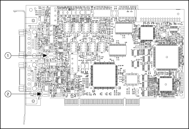
1 Port 1 Termination Resistors 2 Port 2 Termination Resistors Location of Termination Resistors on PCI-CAN/LS2 Card
- Cut and bend the lead wires of the resistors you want to install. Refer to the following figure.

Preparing Lead Wires of Replacement Resistors
- Insert the replacement resistors into the empty sockets.
- Refer to the CAN Hardware and NI-CAN Software for Windows Installation Guide in the jewel case of the program CD to complete the hardware installation.
Replacing the Termination Resistors on the PXI-8460 Board
Complete these steps to replace the termination resistors, after you have determined the correct value in Determining the Necessary Termination Resistance for Your Board.
- Remove the termination resistors on the PXI-8460. The following figure shows the location of the termination resistor sockets on a PXI-8460.

1 Port 1 Termination Resistors 2 Port 2 Termination Resistors Location of Termination Resistors on a PXI-8460
- Cut and bend the lead wires of the resistors you want to install. Refer to the following figure for an example.

Preparing Lead Wires of Replacement Resistors
- Insert the replacement resistors into the empty sockets.
- Refer to the CAN Hardware and NI-CAN Software for Windows Installation Guide in the jewel case of the program CD to complete the hardware installation.
Replacing the Termination Resistors on the PCMCIA-CAN/LS Cable
Complete these steps to replace the termination resistors on the PCMCIA-CAN/LS cable after you have determined the correct value in Determining the Necessary Termination Resistance for Your Board.
- Remove the two termination resistors on the PCMCIA-CAN/LS cable by loosening the pluggable terminal block mounting screws for pins 1 and 2 (RTL) and pins 6 and 7 (RTH).
- Bend and cut the lead wires of the two resistors you want to install, as shown the following figure.
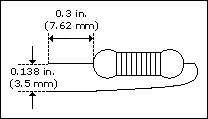
Preparing Lead Wires of PCMCIA-CAN/LS Cable Replacement Resistors
- Mount RTL by inserting the leads of one resistor into pins 1 and 2 of the pluggable terminal block and tightening the mounting screws. Mount RTH by inserting the leads of the second resistor into pins 6 and 7 of the pluggable terminal block and tightening the mounting screws.
- Refer to the CAN Hardware and NI-CAN Software for Windows Installation Guide in the jewel case of the program CD to complete the hardware installation.
Cabling Example
The following figure shows an example of a cable to connect two low-speed CAN devices. For the PCMCIA-CAN/LS cables, only V-, CAN_L, and CAN_H are required to be connected to the bus.
