XS CAN Pinout Cable
XS PCI and PXI Connector Pinout
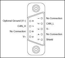
PCI-CAN/XS and PXI-8464 hardware have a 9-pin male D-SUB (DB9) connector for each port.
When an XS port is selected as High-Speed, its connector pinout is identical to a dedicated High-Speed interface as described in High-Speed PCI, PXI, and USB Connector Pinout.
When an XS port is selected as Low-Speed/Fault-Tolerant, its connector pinout is identical to a dedicated Low-Speed/Fault-Tolerant interface as described in Low-Speed/Fault-Tolerant PCI, PXI, and USB Connector Pinout.
When an XS port is selected as Single Wire, its connector pinout is identical to a dedicated Single Wire interface as described in the Single Wire PCI and PXI Connector Pinout.
When an XS port has been selected as External, a different set of signals is routed to the 9-pin D-SUB connector. The following figure shows the 9-pin D-SUB connector pinout for an XS port in External mode.

Pinout for 9-Pin D-SUB Connector
| 9-Pin D-SUB Connector Pin Descriptions | ||
|---|---|---|
| D-SUB Pin | Signal | Description |
| 1 | MODE0 | Digital output signal for external transceiver mode control (XS port in external mode only) |
| 2 | RX | RX0 pin from SJA1000 CAN controller (XS port in external mode only) |
| 3 | GND | Ground |
| 4 | MODE1 | Digital output signal for external transceiver mode control (XS port in external mode only) |
| 5 | No Connection | Do not connect signals to this pin |
| 6 | (GND) | Optional ground |
| 7 | TX | TX0 pin from SJA1000 CAN controller (XS port in external mode only) |
| 8 | STATUS | Digital input signal for external transceiver error reporting (XS port in external mode only) |
| 9 | No Connection | Do not connect signals to this pin |
RX and TX are the serial receive and transmit signals from the SJA1000 CAN controller. GND serves as the reference ground for RX and TX.
MODE0 and MODE1 are digital output signals for controlling the mode selection of an external transceiver. For example, the TJA1041 and TJA1054A have STB and EN input pins to select the transceiver operating mode.
STATUS is a digital input signal for monitoring the status of an external transceiver. For example, the TJA1041 and TJA1054A have an ERR output to report bus fault conditions.
Cabling Requirements for XS CAN
For cabling requirements information, refer to the appropriate section on cabling requirements for High-Speed, Low-Speed/Fault-Tolerant, or Single Wire CAN depending on the XS port mode. Note that due to the different cabling requirements for each physical layer, when switching an XS port, you may also need to change out the cable to meet the network cabling requirements.
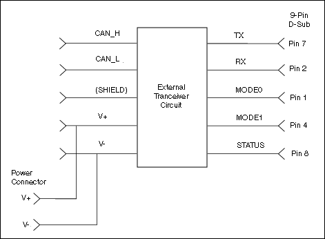
When designing external transceiver circuits for an XS port in external mode, keep the signal connections between the 9-pin D-SUB connector and the transceiver circuit as short as possible. Ideally, the external transceiver circuit should mount directly to the 9-pin D-SUB connector if possible.
External Transceiver Example
The following figure shows an example of an external transceiver circuit for an XS port in External mode.
