Single Wire CAN Pinout Cable
Single Wire PCI and PXI Connector Pinout
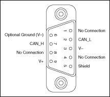
PCI-CAN/XS and PXI-8464 hardware have a 9-pin male D-SUB (DB9) connector for each port. The 9-pin D-SUB connector follows the pinout recommended by CiA DS 102. The following figure shows the 9-pin D-SUB connector pinout.

Pinout for 9-Pin D-SUB Connector
| 9-Pin D-SUB Connector Pin Descriptions | ||
|---|---|---|
| D-SUB Pin | Signal | Description |
| 1 | No Connection | — |
| 2 | CAN_L | CAN_L bus line |
| 3 | V- | CAN reference ground |
| 4 | No Connection | — |
| 5 | (Shield) | Optional CAN shield |
| 6 | (V-) | Optional CAN reference ground |
| 7 | CAN_H | CAN_H bus line |
| 8 | No Connection | — |
| 9 | (V+) | Optional CAN power supply if bus power or external VBAT is required |
CAN_H and CAN_L are signals lines that carry the data on the CAN network. These signals should be connected using twisted-pair cable.
V- serves as the reference ground for CAN_H and CAN_L.
V+ supplies bus power to the CAN physical layer if external power is required. All Low-Speed/Fault-Tolerant Series 2 PCI and PXI hardware is powered internally, so it is not necessary to supply V+ unless you have configured the VBAT jumper for EXT.
Shield is an optional connection when using a shielded CAN cable. Connecting the optional CAN shield may improve signal integrity in a noisy environment.
PCMCIA-CAN Connector Pinout
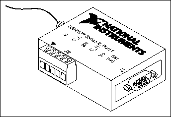
PCMCIA-CAN cables have both a 9-pin male D-SUB and Combicon-style pluggable screw terminal connector for each port. The following figure shows the end of a PCMCIA-CAN cable. The arrow points to pin 1 of the 5-pin screw terminal block. All of the signals on the 5-pin screw terminal are connected directly to the corresponding pins on the 9-pin D-SUB.

PCMCIA-CAN Cable
| PCMCIA-CAN Cable Connector Pin Descriptions | |||
|---|---|---|---|
| D-SUB Pin | Combicon Pin | Signal | Description |
| 1 | — | No Connection | — |
| 2 | 2 | No Connection | — |
| 3 | 1 | V- | CAN reference ground |
| 4 | — | No Connection | — |
| 5 | 3 | (Shield) | Optional CAN shield |
| 6 | — | (V-) | Optional CAN reference ground |
| 7 | 4 | CAN_H | CAN_H bus line |
| 8 | — | No Connection | — |
| 9 | 5 | (V+) | CAN power supply |
CAN_H is the signal line that carries the data on the CAN network.
V- serves as the reference ground for CAN_H.
V+ supplies bus power to the Single Wire CAN transceiver.
Shield is an optional connection when using a shielded CAN cable. Connecting the optional CAN shield may improve signal integrity in a noisy environment.
Cabling Requirements for Single Wire CAN
The number of nodes on the network, the total cable length of the system, the bus loading of each node, and the clock tolerance are all interrelated. It is therefore the responsibility of the system designer to factor in all of the above parameters when designing a Single Wire CAN network. The SAE J2411 standard provides some recommended specifications that can help in making these decisions:
Cable Length
There shall be no more than 60 m between any two network system ECU nodes.
Number of Devices
As stated previously, the maximum number of Single Wire CAN nodes allowed on the network depends on the electrical characteristics of the devices and cable. If all of the devices and cables meet the requirements of J2411, between 2 and 32 devices may be networked together.
Termination (Bus Loading)
NI Single Wire CAN hardware includes a built-in 9.09 k load resistor as specified by J2411.
Cabling Example
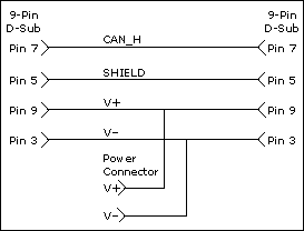
The following figure shows an example of a cable to connect two Single Wire CAN devices.
