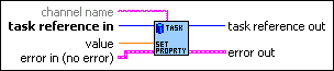
CAN Set Property.vi
From NI-CAN
CAN Set Property.vi
Purpose
Set a property for the task, or a single channel within the task. The poly VI selection determines the property to set.
To select the property, right-click the VI, go to Select Type and select the property by name. For LabVIEW 7.0 and later, you can right-click the VI and select Visible Items»Poly VI Selector to select the property from within the diagram.
Format
Inputs
| task reference in is the task reference from the previous NI-CAN VI. The task reference is originally returned from VIs such as CAN Initialize.vi or CAN Create Message.vi, and then wired through subsequent VIs. | |||||||
channel name specifies an individual channel within the task. The default (unwired) value of channel name is empty, which means that the property applies to the entire task, not a specific channel. Properties that begin with the word Channel or Message do not apply to the entire task, but an individual channel or message within the task. For these channel-specific properties, you must wire the name of a channel from channel list into the channel name input. For properties that do not begin with the word Channel or Message, you must leave channel name unwired (empty). | |||||||
The poly input value specifies the property value. You select the property to set as value by selecting the Poly VI type. The data type of value is also determined by the Poly VI selection. For information on the different properties provided by CAN Get Property, refer to the Poly VI Types section. To select the property, right-click the VI, go to Select Type and select the property by name. | |||||||
Error in describes error conditions occurring before the VI executes. If an error has already occurred, the VI returns the value of the Error in cluster in Error out.
|
Outputs
| task reference out is the same as task reference in. Wire the task reference to subsequent VIs for this task. | |||||||
Error out describes error conditions. If the Error in cluster indicated an error, the Error out cluster contains the same information. Otherwise, Error out describes the error status of this VI.
|
Description
You cannot set a property while the task is running. If you need to change a property prior to starting the task, you cannot use CAN Init Start.vi. First, call CAN Initialize.vi, followed by CAN Set Property and then CAN Start.vi. After you start the task, you also can change a property by calling CAN Stop.vi, followed by CAN Set Property, and then CAN Start again.
Poly VI Types
|
The Behavior After Final Output property applies only to tasks initialized with mode of Output, and sample rate greater than zero. The value specifies the behavior to perform after the final periodic sample is transmitted. Behavior After Final Output uses the following values: Repeat Final Sample Transmit messages for the final sample(s) repeatedly. The final messages are transmitted periodically as specified by sample rate. If there is significant delay between subsequent calls to CAN Write.vi, this value means that periodic messages continue between CAN Write calls, and messages with the data of the final sample will be repeated on the network. Repeat Final Sample is the default value of the Behavior After Final Output property. Cease Transmit Cease transmit of messages until the next call to CAN Write. If there is significant delay between subsequent calls to CAN Write, this value means that periodic messages cease between CAN Write calls, and the data of the final sample will not be repeated on the network. | |||||||
Channel Default Value Sets the default value of the channel in scaled floating-point units. For information on how the Channel Default Value is used, refer to CAN Read.vi and CAN Write.vi. The value of this property is originally set within MAX. If the channel is initialized directly from a CAN database, the value is 0.0 by default, but it can be changed using CAN Set Property. | |||||||
|
Sets the rate (in MHz) of the external clock that is exported to the CAN card. The values for this property are: 20 MHz (20 decimal) When synchronizing 2 CAN cards or synchronizing a CAN card with an E-Series DAQ card, the 20 MHz master timebase rate is to be used. By default, this property is set to 20 MHz. Transmit messages for the final sample(s) repeatedly. The final messages are transmitted periodically as specified by sample rate. 10 MHz (10 decimal) The master timebase rate should be set to 10 MHz when synchronizing a CAN card with an M-Series DAQ card. The M-Series DAQ card can export a 20 MHz clock but it does this by using one of its two counters. If your CAN-DAQ application does not use the 2 DAQ counters then, you can leave the timebase rate set to 20 MHz (default). This property can be set either before or after calling CAN Connect Terminals.vi to connect the RTSI_CLK to Master Timebase. However, this property must always be called prior to starting the task. This property is applicable only to PCI and PXI Series 2 cards. For PCMCIA cards, setting this attribute will return an error. On PXI cards, if PXI_CLK10 is routed to the Master Timebase, then the rate is fixed at 10 MHz (it over-rides any previous setting of this property). Setting this property for Series 1 cards will also result in a NI-CAN error. |
|||||||
|
Sets the format of the timestamps reported by the on-board timer on the CAN card. The default value for this property is Absolute. The values for this property are: 0 (Absolute) Sets the timestamp format to absolute. In the absolute format, the timestamp returned by NI-CAN read functions is the LabVIEW date/time format (DBL representing the number of seconds elapsed since 12:00 a.m., Friday, January 1, 1904). 1 (Relative) Sets the timestamp format to relative. In the relative format, the timestamp returned by the NI-CAN read functions will be zero based (DBL representing the number of seconds since the CAN controller for that task was started). A typical use case for this property would be if data received from two RTSI synchronized CAN cards is to be correlated. For that use case, this property must be set to 1 for all of the CAN cards being synchronized. Setting this property on one port of a 2-port card will also reset the timestamp of the second port, since resetting the timestamp on the CAN port involves resetting the on-board timer. This property should be set prior to starting any tasks on the CAN card. |
|||||||
Interface Baud Rate Sets the baud rate in use by the Interface. This property applies to all tasks initialized with the Interface. You can specify the following basic baud rates as the numeric rate: 33333, 83333, 100000, 125000, 200000, 250000, 400000, 500000, 800000, and 1000000. You can specify advanced baud rates as 8000XXYY hex, where YY is the value of Bit Timing Register 0 (BTR0), and XX is the value of Bit Timing Register 1 (BTR1) of the CAN controller. For more information, refer to the Interface Properties dialog in MAX. The value of this property is originally set within MAX. | |||||||
Interface Listen Only? Sets a Boolean value that indicates whether the listen only feature of the Philips SJA1000 CAN controller is enabled (true) or disabled (false). This property applies to all tasks initialized with the Interface. If Interface Listen Only? is False, the Interface can transmit CAN messages; therefore, CAN Write.vi operates normally. When CAN messages are received by the Interface, those messages are acknowledged. Because False is the behavior specified in the CAN specification, it is the default value of Interface Listen Only?. If Interface Listen Only? is True, the Interface cannot transmit CAN messages; therefore, CAN Write.vi returns an error. When CAN messages are received by the Interface, those messages are not acknowledged. The Philips SJA1000 CAN controller enters error passive state when listen only is enabled (but no error-passive warning is returned). The True value of Interface Listen Only? enables passive monitoring of network traffic, which can be useful for debugging scenarios in which only one device exists on the network. Since the listen only feature requires the Philips SJA1000 CAN controller, this property is supported on Series 2 NI CAN hardware only. If you are using Series 1 NI CAN hardware, an attempt to set this property returns error nctErrRequiresNewSeries (code BFF6210D hex, status T). | |||||||
Interface Self Reception? Specifies whether to echo successfully transmitted CAN frames as received frames. Each reception occurs just as if the frame were received from another CAN device. This enables you to initialize the same channels for both input and output. For self reception to operate properly, another CAN node must receive and acknowledge each transmit. False disables self reception mode (default), and True enables self reception mode. The self reception mode is not available on the Intel 82527 CAN controller used by Series 1 CAN hardware. For Series 1 hardware, this property must be left at its default (False). | |||||||
|
Specifies the filter comparator for the Philips SJA1000 CAN controller on all Series 2 CAN hardware. This property is not supported for Series 1 hardware (returns error). This property specifies a comparator value that is checked against the ID, RTR, and data bits. The Interface Series 2 Mask determines the applicable bits for comparison. The default value of this property is zero. The mapping of bits in this property to the ID, RTR, and data bits of incoming frames is determined by the value of the Interface Series 2 Filter Mode property. The Series 2 filter mode determines the format of this property as well as the Series 2 mask. | |||||||
Interface Series 2 Filter Mode All Series 2 hardware uses the Philips SJA1000 CAN controller. The Philips SJA1000 CAN controller provides sophisticated filtering of received frames. This property specifies the filtering mode, which is used in conjunction with the Interface Series 2 Mask and Interface Series 2 Comparator properties. This property is not supported for Series 1 hardware (returns error). Since the format of the Series 2 filters is very specific to the Philips SJA1000 CAN controller, National Instruments cannot guarantee compatibility for this property on future hardware series. When using this property in the application, it is best to get the Hardware Series property to verify that the CAN hardware is Series 2. The filtering specified by the Series 2 filter properties applies to all input tasks for that interface. For example, if you specify filters that discard ID 5, then open an Input task to receive channels of ID 5, the task will not receive data. The default value for this property is Single Standard. The values for this property are summarized below. For detailed information on each value, including the format of the Interface Series 2 Mask and Interface Series 2 Comparator properties for each mode, refer to Series 2 Filter Mode attribute in the ncSetAttr.vi function of the Frame API. Single Standard Filter all standard (11-bit) frames using a single mask/comparator filter. Single Extended Filter all extended (29-bit) frames using a single mask/comparator filter. Dual Standard Filter all standard (11-bit) frames using a two separate mask/comparator filters. If either filter matches the frame, it is received. The frame is discarded only when neither filter detects a match. Dual Extended Filter all extended (29-bit) frames using a two separate mask/comparator filters. If either filter matches the frame, it is received. The frame is discarded only when neither filter detects a match. | |||||||
|
Specifies the filter mask for the Philips SJA1000 CAN controller on all Series 2 CAN hardware. This property is not supported for Series 1 hardware (returns error). This property specifies a bit mask that determines the ID, RTR, and data bits that are compared. If a bit is clear in the mask, the corresponding bit in the Interface Series 2 Comparator is checked. If a bit in the mask is set, that bit is ignored for the purpose of filtering (don't care). The default value of this property is hex FFFFFFFF, which means that all messages are received. The mapping of bits in this property to the ID, RTR, and data bits of incoming frames is determined by the value of the Interface Series 2 Filter Mode property. The Series 2 filter mode determines the format of this property as well as the Series 2 comparator. | |||||||
Interface Single Shot Transmit? Specifies whether to retry failed CAN frame transmissions (Series 2 only). If Interface Single Shot Transmit? is False (default), failed transmissions retry as defined in the CAN specification. If a CAN frame is not transmitted successfully, the CAN controller will immediately retry. If Interface Single Shot Transmit? is True, all transmissions are single shot. If a CAN frame is not transmitted successfully, the CAN controller will not retry. The single-shot transmit feature is not available on the Intel 82527 CAN controller used by Series 1 CAN hardware (set returns error). | |||||||
Interface Transceiver External Outputs Sets the transceiver external outputs for the interface that was initialized for the task. Series 2 XS cards enable connection of an external transceiver. For an external transceiver, this property allows you to set the output voltage on the MODE0 and MODE1 pins of the CAN port, and it allows you control the sleep mode of the on-board CAN controller chip. For many models of CAN transceiver, EN and NSTB pins control the transceiver mode, such as whether the transceiver is sleeping or communicating normally. For such transceivers, you can wire the EN and NSTB pins to the MODE0 and MODE1 pins of the CAN port. The default value of this property is 00000003 hex. For many models of transceiver, this specifies normal communication mode for the transceiver and CAN controller chip. If the transceiver requires a different MODE0/MODE1 combination for normal mode, you can use external inverters to change the default 5 V to 0 V. This property is supported for Series 2 XS cards only. This property is not supported when the Interface Transceiver Type is any value other than External. To control the mode of an internal transceiver, use the Interface Transceiver Mode property. This property uses a bit mask. Use bitwise OR operations to set multiple values. 00000001 hex MODE0 Set this bit to drive 5 V on the MODE0 pin. This is the default value. This bit is set automatically when a remote wakeup is detected. Clear this bit to drive 0 V on the MODE0 pin. 00000002 hex MODE1 Set this bit to drive 5 V on the MODE1 pin. This is the default value. This bit is set automatically when a remote wakeup is detected. Clear this bit to drive 0 V on the MODE1 pin. 00000100 hex Sleep CAN controller chip Set this bit to place the CAN controller chip into sleep mode. This bit controls the mode of the CAN controller chip (sleep or normal), and the independent MODE0/MODE1 bits control the mode of the external transceiver. When you set this bit to place the CAN controller into sleep mode, you typically specify MODE0/MODE1 bits that place the external transceiver into sleep mode as well. When the CAN controller is asleep, a remote wakeup will automatically place the CAN controller into its normal mode of communication. In addition, the MODE0/MODE1 pins are restored to their default values of 5 V. Therefore, a remote wakeup causes this property to change from the value that you set for sleep mode, back to its default 00000003 hex. You can determine when this has occurred by getting Interface Transceiver External Outputs using CAN Get Property.vi. For more information on remote wakeup, refer to the Interface Transceiver Mode property for internal transceivers. Clear this bit to place the CAN controller chip into normal communication mode. If the CAN controller was previously in sleep mode, this performs a local wakeup to restore communication. | |||||||
|
Sets the transceiver mode for the interface that was initialized for the task. The transceiver mode controls whether the transceiver is asleep or communicating, as well as other special modes. This property is supported on Series 2 cards only. For Series 2 cards for the PCMCIA form factor, this property requires a corresponding Series 2 cable (dongle). For information on how to identify the series of the PCMCIA cable, refer to Series 2 Vs. Series 1. For Series 2 XS cards, this property is not supported when the Interface Transceiver Type is External. To control the mode of an external transceiver, use the Interface Transceiver External Outputs property. The default value for this property is Normal. This property uses the following values: Normal Set transceiver to normal communication mode. If you set Sleep mode previously, this performs a local wakeup of the transceiver and CAN controller chip. Sleep Set transceiver and the CAN controller chip to sleep (or standby) mode. If the transceiver supports multiple sleep/standby modes, the NI CAN hardware implementation ensures that all of those modes are equivalent with regard to the behavior of the transceiver on the network. For more information on the physical specifications for normal and sleep modes for each transceiver, refer to NI CAN and LIN Hardware. You can set Sleep mode only while the interface is communicating. If at least one task for the interface has not been started (such as with CAN Start.vi), setting the transceiver mode to Sleep will return an error. When the interface enters sleep mode, communication is not possible until a wakeup occurs. All pending frame transmissions are deferred until the wakeup occurs. The transceiver and CAN controller wake from sleep mode when either a local wakeup or remote wakeup occurs. If you set Sleep mode when the CAN controller is actively transmitting a frame (that is, won arbitration), the interface will not enter Sleep mode until the frame is transmitted successfully (acknowledgement detected). A local wakeup occurs when the application sets the transceiver mode to Normal (or some other communication mode). A remote wakeup occurs when a remote node transmits a CAN frame (referred to as the wakeup frame). The wakeup frame wakes up the transceiver and CAN controller chip of the NI CAN interface. The wakeup frame is not received or acknowledged by the CAN controller chip. When the wakeup frame ends, the NI CAN interface enters Normal mode, and again receives and transmits CAN frames. If the node that transmitted the wakeup frame did not detect an acknowledgement (such as if other nodes were also waking), it will retry the transmission, and the retry will be received by the NI CAN interface. For a remote wakeup to occur for Single Wire transceivers, the node that transmits the wakeup frame must first place the network into the Single Wire Wakeup Transmission mode by asserting a higher voltage (typically 12 V). For more information, refer to Single Wire Wakeup mode. When the local or remote wakeup occurs, frame transmissions resume from the point at which the original Sleep was set. You can detect when a remote wakeup occurs by using CAN Get Property.vi with the Interface Transceiver Mode property. Set Single Wire transceiver to Wakeup Transmission mode. This mode is supported on Single Wire (SW) ports only. The Single Wire Wakeup Transmission mode drives a higher voltage level on the network to wake up all sleeping nodes. Other than this higher voltage, this mode is similar to Normal mode. CAN frames can be received and transmitted normally. Since you use the Single Wire Wakeup mode to wake up other nodes on the network, it is not typically used in combination with Sleep mode for a given interface. The timing of how long the wakeup voltage is driven is controlled entirely by the application. Your application will typically change to Single Wire Wakeup mode, transmit a wakeup frame, then return to Normal mode. The following sequence demonstrates a typical sequence of steps for sleep and wakeup between two Single Wire NI CAN interfaces. The sequence assumes that CAN0 is the sleeping node, and CAN1 originates the wakeup.
Single Wire High-Speed Set Single Wire transceiver to High-Speed Transmission mode. This mode is supported on Single Wire (SW) ports only. The Single Wire High-Speed Transmission mode disables the internal waveshaping function of the transceiver, which allows baud rates up to 100 kbytes/s to be used. The disadvantage versus Normal (which allows up to 40 kbytes/s baud) is degraded EMC performance. Other than the disabled waveshaping, this mode is similar to Normal mode. CAN frames can be received and transmitted normally. This mode has no relationship to High-Speed (HS) transceivers. It is merely a higher speed mode of the Single Wire (SW) transceiver, typically used for downloading large amounts of data to a node. The Single Wire transceiver does not support use of this mode in conjunction with Sleep mode. For example, a remote wakeup cannot transition from Sleep to this Single Wire High-Speed mode. | |||||||
|
For XS Software Selectable Physical Layer cards that provide a software-switchable transceiver, the Interface Transceiver Type property sets the type of transceiver. When the transceiver is switched from one type to another, NI-CAN ensures that the switch is undetectable from the perspective of other nodes on the network. The default value for this property is specified within MAX. If you change the transceiver type in MAX to correspond to the network in use, you can avoid setting this property within the application. This property applies to all tasks initialized with the same interface. You cannot set this property for Series 1 hardware, or for Series 2 hardware other than XS (fixed HS, LS, or SW cards). This property uses the following values: High-Speed Switch the transceiver to High-Speed (HS). Low-Speed/Fault-Tolerant Switch the transceiver to Low-Speed/Fault-Tolerant (LS). Single Wire Switch the transceiver to Single Wire (SW). External Switch the transceiver to External. The External type allows you to connect a transceiver externally to the interface. For more information on connecting transceivers externally, refer to NI CAN and LIN Hardware. When this transceiver type is selected, you can use the Transceiver External Outputs and Transceiver External Inputs properties to access the external mode and status pins of the connector. Disconnect Disconnect the CAN controller chip from the connector. This value is used when you physically switch an external transceiver. You first set Interface Transceiver Type to Disconnect, then switch from one external transceiver to another, then set Interface Transceiver Type to External. For more information on connecting transceivers externally, refer to NI CAN and LIN Hardware. | |||||||
|
Sets the Virtual Bus Timing of the virtual device. Interface Virtual Bus Timing uses the following values: 0 (False) Virtual Bus Timing is turned off. By turning Virtual Bus Timing off, the CAN bus simulation is disabled and CAN frames are copied from the write queue of one virtual interface to the read queue of the second virtual interface. This setting is useful if you desire to only convert frames to channels or vice versa and not simulate actual CAN bus communication. 1 (True) Virtual Bus Timing is turned on (default). By turning Virtual Bus Timing on, frame timestamps are recalculated as they transfer across the virtual bus. This mode is useful when you want the virtual bus to behave as much like a real bus as possible. If this property is set on real hardware, an error will be returned. Virtual Bus Timing has to be set to the same value on both virtual interfaces. This property must be set prior to starting the virtual interface. Refer to Frame to Channel Conversion for more information. |
|||||||
Message Multiple Frame Distribution Sets the Message Multiple Frame Distribution property which is used to determine if the CAN frames associated to a group of mode dependent channels are sent even spaced or in burst mode. Message Multiple Frame Distribution uses the following values:
| |||||||
|
Sets a time in milliseconds to wait for samples. The default value is zero. For all task configurations, the Timeout specifies the time that Read will wait for the start trigger. If the application does not use CAN Connect Terminals, the start trigger occurs when the task starts (CAN Start). If you connect a start trigger from a RTSI line or other source, Timeout specifies the number of milliseconds to wait. Timeout of zero means to wait up to 10 seconds for the start trigger. Use of the Timeout property depends on the initialized mode of the task:
| |||||||
|
Sets the value that is returned on time stamped read for mode dependent channels that have not been received with the most recent CAN frame associated with the CAN message. This property applies only to mode dependent channels that are read with the time stamped read operation. For more information, refer to Mode Dependent Channels. |