High-Speed CAN Pinout Cable
High-Speed PCI, PXI, and USB Connector Pinout
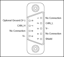
PCI-CAN, PXI-8461, USB-8473, and USB-8473s hardware have a 9-pin male D-SUB (DB9) connector for each port. The 9-pin D-SUB connector follows the pinout recommended by CiA DS 102. The following figure shows the 9-pin D-SUB connector pinout.

Pinout for 9-Pin D-SUB Connector
| Pinout for 9-Pin D-SUB Connector | ||
|---|---|---|
| D-SUB Pin | Signal | Description |
| 1 | No Connection | — |
| 2 | CAN_L | CAN_L bus line |
| 3 | V- | CAN reference ground |
| 4 | No Connection | — |
| 5 | (Shield) | Optional CAN shield |
| 6 | (V-) | Optional CAN reference ground |
| 7 | CAN_H | CAN_H bus line |
| 8 | No Connection | — |
| 9 | (V+) | Optional CAN power supply if bus power or external VBAT is required |
CAN_H and CAN_L are signals lines that carry the data on the CAN network. These signals should be connected using twisted-pair cable.
V- serves as the reference ground for CAN_H and CAN_L.
V+ supplies bus power to the CAN physical layer if external power is required. All High-Speed Series 2 PCI, PXI, and USB hardware is powered internally, so it is not necessary to supply V+, unless you have configured the VBAT jumper for EXT.
Shield is an optional connection when using a shielded CAN cable. Connecting the optional CAN shield may improve signal integrity in a noisy environment.
PCMCIA Connector Pinout
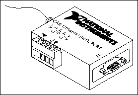
PCMCIA-CAN cables have both a 9-pin male D-SUB and Combicon-style pluggable screw terminal connector for each port. The following figure shows the end of a PCMCIA-CAN cable. The arrow points to pin 1 of the 5-pin screw terminal block. All of the signals on the 5-pin screw terminal are connected directly to the corresponding pins on the 9-pin D-SUB.

PCMCIA-CAN Cable
| PCMCIA-CAN Cable Connector Pin Descriptions | |||
|---|---|---|---|
| D-SUB Pin | Combicon Pin | Signal | Description |
| 1 | — | No Connection | — |
| 2 | 2 | CAN_L | CAN_L bus line |
| 3 | 1 | V- | CAN reference ground |
| 4 | — | No Connection | — |
| 5 | 3 | (Shield) | Optional CAN shield |
| 6 | — | (V-) | Optional CAN reference ground |
| 7 | 4 | CAN_H | CAN_H bus line |
| 8 | — | No Connection | — |
| 9 | 5 | No Connection | — |
CAN_H and CAN_L are signal lines that carry the data on the CAN network. These signals should be connected using twisted-pair cable.
V- serves as the reference ground for CAN_H and CAN_L.
Shield is an optional connection when using a shielded CAN cable. Connecting the optional CAN shield may improve signal integrity in a noisy environment.
Cabling Requirements for High-Speed CAN
Cables should meet the physical medium requirements specified in ISO 11898, shown in the following table.
Belden cable (3084A) meets all of those requirements, and should be suitable for most applications.
| ISO 11898 Specifications for Characteristics of a CAN_H and CAN_L Pair of Wires | |
|---|---|
| Characteristic | Value |
| Impedance | 108  minimum, 120 minimum, 120  nominal, 132 nominal, 132  maximum maximum |
| Length-related resistance | 70 m /m nominal
 |
| Specific line delay | 5 ns/m nominal |
Cable Lengths
The allowable cable length is affected by the characteristics of the cabling and the desired bit transmission rates. Detailed cable length recommendations can be found in the ISO 11898, CiA DS 102, and DeviceNet specifications.
ISO 11898 specifies 40 m total cable length with a maximum stub length of 0.3 m for a bit rate of 1 Mb/s. The ISO 11898 specification says that significantly longer cable lengths may be allowed at lower bit rates, but each node should be analyzed for signal integrity problems.
The following table lists the DeviceNet cable length specifications.
| DeviceNet Cable Length Specifications | ||
|---|---|---|
| Bit Rate | Thick Cable | Thin Cable |
| 500 kb/s | 100 m | 100 m |
| 250 kb/s | 200 m | 100 m |
| 100 kb/s | 500 m | 100 m |
Number of Devices
The maximum number of devices depends on the electrical characteristics of the devices on the network. If all of the devices meet the requirements of ISO 11898, at least 30 devices may be connected to the bus. Higher numbers of devices may be connected if the electrical characteristics of the devices do not degrade signal quality below ISO 11898 signal level specifications. If all of the devices on the network meet the DeviceNet specifications, 64 devices may be connected to the network.
Cable Termination
The pair of signal wires (CAN_H and CAN_L) constitutes a transmission line. If the transmission line is not terminated, each signal change on the line causes reflections that may cause communication failures.
Because communication flows both ways on the CAN bus, CAN requires that both ends of the cable be terminated. However, this requirement does not mean that every device should have a termination resistor. If multiple devices are placed along the cable, only the devices on the ends of the cable should have termination resistors. Refer to the following figure for an example of where termination resistors should be placed in a system with more than two devices.

Termination Resistor Placement
The termination resistors on a cable should match the nominal impedance of the cable. ISO 11898 requires a cable with a nominal impedance of 120  ; therefore, a 120
  resistor should be used at each end of the cable. Each termination resistor should be capable of dissipating 0.25 W of power.
Cabling Example
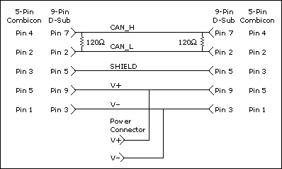
The following figure shows an example of a cable to connect two CAN devices. For the internal power configuration, no V+ connection is required.
