LIN
This section describes the USB-LIN hardware.
USB-LIN Connector Pinout
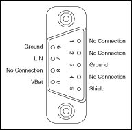
USB-8476 and USB-8476s hardware has a 9-pin male D-Sub (DB9) connector for connection to the LIN bus. The following figure shows the 9-pin D-Sub connector pinout.

| 9-Pin D-SUB Connector Pin Descriptions | ||
|---|---|---|
| D-SUB Pin | Signal | Description |
| 1 | No Connection | — |
| 2 | No Connection | — |
| 3 | Ground | LIN reference ground. |
| 4 | No Connection | — |
| 5 | (Shield) | Optional LIN shield. Connecting the optional LIN shield may improve signal integrity in a noisy environment. |
| 6 | Ground | LIN reference ground. |
| 7 | LIN | Signal line that carries the data on the LIN. |
| 8 | No Connection | — |
| 9 | VBat | Supplies bus power to the LIN physical layer, as required by the LIN spec. All USB-LIN interfaces require bus power of 8-18 VDC. |
Cabling Requirements for LIN Specifications (LIN)
This section describes cabling requirements for LIN.
Cable Specifications
LIN cables should meet the physical medium requirement of a bus RC time constant of 5 microseconds. For detailed formulas for calculating this value, refer to the Line Characteristics section of the LIN specification.
Belden cable (3084A) and other unterminated CAN/Serial quality cables meet these requirements, and should be suitable for most applications.
Cable Lengths
The maximum allowable cable length is 40 meters, per the LIN specification.
Number of Devices
The maximum number of devices on a LIN bus is 16, per the LIN specification.
Termination
LIN cables require no termination, as nodes are terminated at the transceiver. Slave nodes are typically pulled up from the LIN bus to VBat with a 30 KΩ resistance and a serial diode. This termination is usually integrated into the transceiver package. The master node requires a 1 KΩ resistor and serial diode between the LIN bus and VBat.
On NI USB-LIN products, master termination is software selectable and can be enabled with the Termination attribute. For more information refer to the ncSetAttribute function within the Frame API.