Linking Objects
From Diagram Designer
|
|
Linking Objects |
|
|
|
|
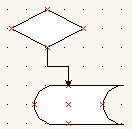
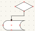
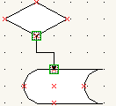
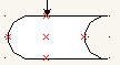
One of the features of Diagram Designer is object linking. Most objects have link points (the little red Xs), either built-in or user defined, which allow linking of lines and connectors. Once a line (or connector) is linked to an object, moving that object also moves or re-calculates the line or connector. An example of this:
|
|
|
|
|
Linking lines and connectors to objects can be a little tricky; basically, the procedure is as follows:
|
 |
|
|
|
 |
|
 |
|
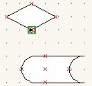
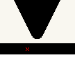
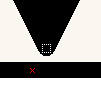
If a line or connector is linked to objects, selecting that line should cause the green boxes to appear. If they do not appear, the endpoints of the line or connector must be moved to a location directly over the link point - some magnification may help in this operation.
| 1. Normal view (100%) | 2. Zoom 1600% | 3. Select connector | 4. Move endpoint to link point. Link is created. |
 |
 |
 |
 |
Using the Connect links tool (Diagram menu) will force link connections also, but only for those lines and connectors whose endpoints lie exactly (ie. within the internal accuracy of Diagram Designer) over a link point.
|
|
|