Owning Palette: Analytical PID Design VI
Installed With: Control Design and Simulation Module
Calculates the proportional gain KP, integral gain KI, and derivative gain KD that stabilize the specified controller model(s). This VI accepts discrete single-input single-output (SISO) models only. However, you can specify more than one SISO model at a time by using the two-dimensional transfer function(s) array control of the CD Construct Transfer Function Model VI.This VI is based on algorithms and techniques described in the following resource: Datta, A.; M. T. Ho; and S. P. Bhattacharyya. 2000. Structure and synthesis of PID controllers. London: Springer-Verlag.
Use the pull-down menu to select an instance of this VI.
 Place on the block diagram Place on the block diagram |  Find on the Functions palette Find on the Functions palette |
CD Design PID for Discrete Systems (State-Space)

 | State-Space Model specifies a state-space representation of the controller model for which this VI calculates the PID gains. | ||||||
 | Sampling Specifications specifies the options relating to how this VI divides and samples the common K3 range.
Refer to the Details section for more information about these steps.
| ||||||
 | Min Gain and Phase Margins specifies the optional performance constraints on the PID controller model. If you specify a value of 0 for either of these constraints, this VI does not attempt to verify that constraint. If you specify nonzero a value for either parameter, this VI returns PID gain values that satisfy the performance constraint(s).
| ||||||
 | error in describes error conditions that occur before this VI or function runs.
The default is no error. If an error occurred before this VI or function runs, the VI or function passes the error in value to error out. This VI or function runs normally only if no error occurred before this VI or function runs. If an error occurs while this VI or function runs, it runs normally and sets its own error status in error out. Use the Simple Error Handler or General Error Handler VIs to display the description of the error code.
Use exception control to treat what is normally an error as no error or to treat a warning as an error.
Use error in and error out to check errors and to specify execution order by wiring error out from one node to error in of the next node.
| ||||||
 | Design PID Gains returns the PID gain values that are closest to the centroid, or average, of all intersecting planes. These gain values guarantee simultaneous closed-loop stability for all specified models. If you specified nonzero Min Gain and Phase Margins, these gain values also satisfy those performance constraints.
The Design PID Gains tuple is a subset of the Stable Set Interior Points. If the Design PID Gains is acceptable, you can choose an alternate tuple from the Stable Set Interior Points parameter. This parameter is a cluster of three one-dimensional arrays. The nth element of each array corresponds to the KP, KI, or KD value of a single set.
| ||||||
 | Stable Set Boundary returns the boundary between the stable and unstable PID gain values. All gain values within the stable boundary are guaranteed to be stable for the PID controller.
| ||||||
 | Stable Set Interior Points returns the set of gain values that lie within the Stable Set Boundary. All gain values within the stable boundary are guaranteed to be stable for the PID controller. Additionally, all gain values are guaranteed to meet any performance criteria you specified by using the Min Gain and Phase Margins parameter. | ||||||
 | error out contains error information. If error in indicates that an error occurred before this VI or function ran, error out contains the same error information. Otherwise, it describes the error status that this VI or function produces.
Right-click the error out front panel indicator and select Explain Error from the shortcut menu for more information about the error.
|
CD Design PID for Discrete Systems (Transfer Function)

 | Transfer Function Model specifies a transfer function representation of the controller model for which this VI calculates the PID gains. | ||||||
 | Sampling Specifications specifies the options relating to how this VI divides and samples the common K3 range.
Refer to the Details section for more information about these steps.
| ||||||
 | Min Gain and Phase Margins specifies the optional performance constraints on the PID controller model. If you specify a value of 0 for either of these constraints, this VI does not attempt to verify that constraint. If you specify nonzero a value for either parameter, this VI returns PID gain values that satisfy the performance constraint(s).
| ||||||
 | error in describes error conditions that occur before this VI or function runs.
The default is no error. If an error occurred before this VI or function runs, the VI or function passes the error in value to error out. This VI or function runs normally only if no error occurred before this VI or function runs. If an error occurs while this VI or function runs, it runs normally and sets its own error status in error out. Use the Simple Error Handler or General Error Handler VIs to display the description of the error code.
Use exception control to treat what is normally an error as no error or to treat a warning as an error.
Use error in and error out to check errors and to specify execution order by wiring error out from one node to error in of the next node.
| ||||||
 | Design PID Gains returns the PID gain values that are closest to the centroid, or average, of all intersecting planes. These gain values guarantee simultaneous closed-loop stability for all specified models. If you specified nonzero Min Gain and Phase Margins, these gain values also satisfy those performance constraints.
The Design PID Gains tuple is a subset of the Stable Set Interior Points. If the Design PID Gains is acceptable, you can choose an alternate tuple from the Stable Set Interior Points parameter. This parameter is a cluster of three one-dimensional arrays. The nth element of each array corresponds to the KP, KI, or KD value of a single set.
| ||||||
 | Stable Set Boundary returns the boundary between the stable and unstable PID gain values. All gain values within the stable boundary are guaranteed to be stable for the PID controller.
| ||||||
 | Stable Set Interior Points returns the set of gain values that lie within the Stable Set Boundary. All gain values within the stable boundary are guaranteed to be stable for the PID controller. Additionally, all gain values are guaranteed to meet any performance criteria you specified by using the Min Gain and Phase Margins parameter. | ||||||
 | error out contains error information. If error in indicates that an error occurred before this VI or function ran, error out contains the same error information. Otherwise, it describes the error status that this VI or function produces.
Right-click the error out front panel indicator and select Explain Error from the shortcut menu for more information about the error.
|
CD Design PID for Discrete Systems (Zero-Pole-Gain)

 | Zero-Pole-Gain Model specifies a zero-pole-gain representation of the controller model for which this VI calculates the PID gains. | ||||||
 | Sampling Specifications specifies the options relating to how this VI divides and samples the common K3 range.
Refer to the Details section for more information about these steps.
| ||||||
 | Min Gain and Phase Margins specifies the optional performance constraints on the PID controller model. If you specify a value of 0 for either of these constraints, this VI does not attempt to verify that constraint. If you specify nonzero a value for either parameter, this VI returns PID gain values that satisfy the performance constraint(s).
| ||||||
 | error in describes error conditions that occur before this VI or function runs.
The default is no error. If an error occurred before this VI or function runs, the VI or function passes the error in value to error out. This VI or function runs normally only if no error occurred before this VI or function runs. If an error occurs while this VI or function runs, it runs normally and sets its own error status in error out. Use the Simple Error Handler or General Error Handler VIs to display the description of the error code.
Use exception control to treat what is normally an error as no error or to treat a warning as an error.
Use error in and error out to check errors and to specify execution order by wiring error out from one node to error in of the next node.
| ||||||
 | Design PID Gains returns the PID gain values that are closest to the centroid, or average, of all intersecting planes. These gain values guarantee simultaneous closed-loop stability for all specified models. If you specified nonzero Min Gain and Phase Margins, these gain values also satisfy those performance constraints.
The Design PID Gains tuple is a subset of the Stable Set Interior Points. If the Design PID Gains is acceptable, you can choose an alternate tuple from the Stable Set Interior Points parameter. This parameter is a cluster of three one-dimensional arrays. The nth element of each array corresponds to the KP, KI, or KD value of a single set.
| ||||||
 | Stable Set Boundary returns the boundary between the stable and unstable PID gain values. All gain values within the stable boundary are guaranteed to be stable for the PID controller.
| ||||||
 | Stable Set Interior Points returns the set of gain values that lie within the Stable Set Boundary. All gain values within the stable boundary are guaranteed to be stable for the PID controller. Additionally, all gain values are guaranteed to meet any performance criteria you specified by using the Min Gain and Phase Margins parameter. | ||||||
 | error out contains error information. If error in indicates that an error occurred before this VI or function ran, error out contains the same error information. Otherwise, it describes the error status that this VI or function produces.
Right-click the error out front panel indicator and select Explain Error from the shortcut menu for more information about the error.
|
CD Design PID for Discrete Systems Details
This VI assumes the following system structure:

where
- z is the discrete time variable.
- G(z) is any proper transfer function that represents the plant you want to control.
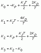
- C(z) is a PID controller with proportional gain KP, integral gain KI, and derivative gain KD. To search for these values, this VI transforms KP, KI, and KD into K1, K2, and K3 by using the following equations:

where
This VI executes the following steps:
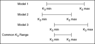
- Calculates a valid K3 range for each specified model. If this VI cannot calculate a valid K3 range for each model, the problem is infeasible, and LabVIEW returns an error.
- Calculates a K3 range that is feasible for all specified models. If this VI cannot calculate this range, the problem is infeasible, and LabVIEW returns an error. The following figure shows an example of steps 1 and 2.
- Divides this common range into a number of points specified by the Num K Grid Points parameter. The following figure shows an example of this step, where n is the Num K Grid Points parameter.

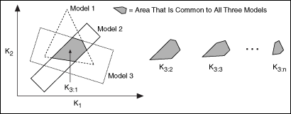
- Calculates two-dimensional polygons at each K3 point. Each polygon corresponds to a specified model. The dimensions of these polygons are K1 on the x-axis and K2 on the y-axis.
- Calculates the intersection between the polygons at each K3 point. The result is a set of two-dimensional polygons, known as slices. Each slice is common to each model at each K3 point. The following figure shows an example of steps 4 and 5.
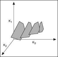
- Lines up each slice in three-dimensional space, where K3 is the third axis. This step approximates a three-dimensional shape that represents the boundary between stable and unstable sets of PID gain values. On this three-dimensional grid, K1 is the y-axis, K2 is the z-axis, and K3 is the x-axis. The following figure shows an example of this step.
- Takes a uniform random sampling of points inside each slice. You specify the total number of points by using the Num Search Points parameter. Each point represents a set of K1, K2, and K3 values.

Note This VI defines a rectangle around the polygon, takes samples of points within the entire rectangle, and keeps only those points that lie inside the slice. The number of discarded points depends on the aspect ratio of the polygon. Because this approach discards points that lie outside the slice, the number of points returned might not match the Num Search Points parameter exactly. The following figure shows an example of this step.
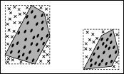
This VI discards points that lie outside the slice. These discarded points are marked with an X in the previous figure.
- Transforms each K1, K2, and K3 value into KP, KI, and KD values.
- This VI returns the set of two-dimensional slices in the Stable Set Boundary parameter. The following figure shows an example stable boundary.
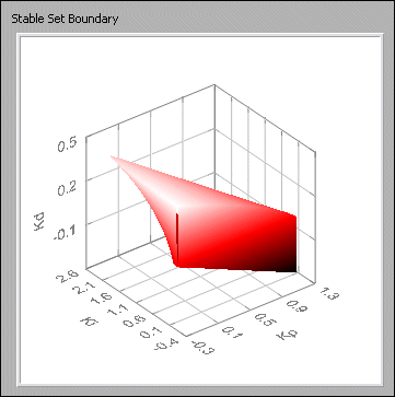
All points within the boundary, as shown in the previous figure, are stable.
- This VI also returns the points within the boundary in the Stable Set Interior Points parameter. The following figure shows a sample set of points.
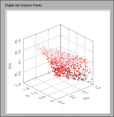
Refer to the following resources for more information about the algorithms and methods this VI uses.
- Keel, L. H., J. I. Rego, and S. P. Bhattacharyya. 2003. A new approach to digital PID controller design. IEEE Transactions on Automatic Control 48, no. 4.
- Keel, L.H., and S.P. Bhattacharyya. 2002. Root counting, phase unwrapping, stability and stabilization of discrete time systems. Linear algebra and its applications 351–2:501–518.
- Ho, Ming-Tzu, G. J. Silva, A. Datta, and S. P. Bhattacharyya. 2004. Real and complex stabilization: stability and performance. Proc. Of the 2004 American Control Conference 5:4126–38.


