Zero-Phase Filtering (Digital Filter Design Toolkit)
From LabVIEW Digital Filter Design Toolkit
Zero-Phase Filtering (Digital Filter Design Toolkit)
Zero-phase filtering helps you eliminate the group delay in the output signal of a filter. All multirate filters you design with the LabVIEW Digital Filter Design Toolkit, except for possible odd-order cascaded integrator comb (CIC) filters, are even-order, linear phase FIR filters. When you use linear phase FIR filters to process signals, the filters return signals with a constant group delay, as shown in the following figure:
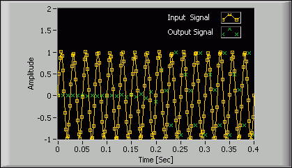
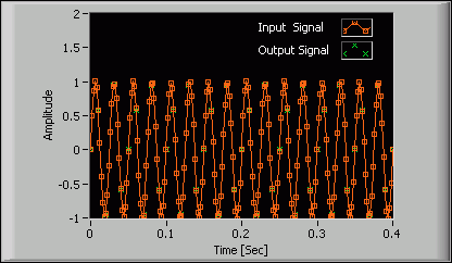
In this figure, you can see that the Output Signal plot contains a constant set of zero values, which denotes the delay between the output and input signals. If you want to eliminate the delay, you can implement the filter as a zero-phase filter by setting the zero phase? input of the Multirate Processing VIs to TRUE. The following figure shows an example of an output signal that has no delay compared with the input signal.
Because zero-phase filters must be noncausal, you cannot achieve zero-phase filtering in real-time signal processing. The Multirate Processing VIs achieve zero-phase by padding and trimming data. For single-block processing, the VIs pad the input data block at the beginning and end and trim the output data so the delay between the input and output is zero. For continuous processing, the VIs trim the initial transition so the delay between the input and the output is zero.
| Note Zero-phase filtering works only with even-order multirate filters. All multirate filters you design using the Digital Filter Design Toolkit, except odd-order CIC filters, are even-order filters. |