Group Delay Compensator (Digital Filter Design Toolkit)
Infinite impulse response (IIR) filters that you design using Butterworth, Chebyshev, or Elliptic methods usually have a nonconstant group delay, which means that they have nonlinear phase or phase distortion. The greatest deviation from a constant group delay typically occurs at the edge of the passband or somewhere in the transition band.
Given a filter with phase distortion, you can cascade the filter with an allpass filter to linearize the phase response in the specified frequency ranges while keeping the magnitude response unchanged.
Let  and
and  denote the group delay of the given filter and the designed allpass filter at the i
th frequency point, respectively. The coefficients vector of the allpass filter
  is determined by the following equation:

where  is the target group delay in all user-defined frequency ranges.
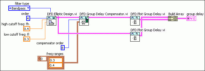
A 4th order elliptic bandpass filter with a passband frequency ranging from 0.3 to 0.4 has nonconstant group delay in the specified passband. The following figure shows how to compensate the filter group delay in the specified passband to be near constant with an 8th order compensator using the DFD Group Delay Compensator VI.

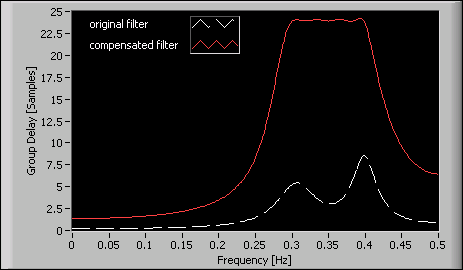
The block diagram in the above figure uses the DFD Plot Group Delay VI to check the group delay response of the filter. The following figure shows the group delay response of the original filter and the compensated filter.

In the previous figure, you can see that the group delay of the compensated filter is fairly constant in the passband frequency ranging from 0.3 to 0.4. The constant value of the group delay indicates that the compensated filter linearly approximates the phase response in the passband. However, compared to the original filter, the compensated filter also increases the delay and filtering computation.