Fixed-Point Filter Design Process (Digital Filter Design Toolkit)
Fixed-point signal processing platforms, such as fixed-point digital signal processors (DSPs) and field-programmable gate arrays (FPGAs), are typically more power-efficient and less expensive than floating-point alternatives. However, fixed-point systems are generally more difficult to design. For example, you must consider the effects of coarser quantizations in fixed-point systems.
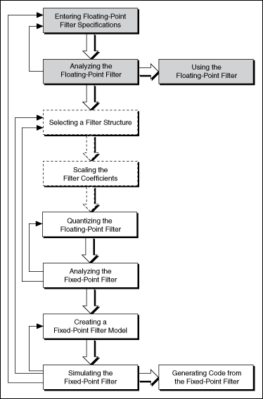
To design a fixed-point filter, you first must design a floating-point filter, also known as a reference filter, that meets the target specifications. In some cases, for example, if you need an infinite impulse response (IIR) filter with a narrow transition band but a high stopband attenuation, you need to design a reference filter that exceeds the target specifications. The excess margin ensures a smooth conversion from a floating-point representation to a fixed-point representation. You then must modify the floating-point filter to accommodate the finite-precision constraints of the target platform while still trying to meet the target specifications. The following figure illustrates the fixed-point filter design process. The grey boxes illustrate the floating-point filter design process, the dotted lines represent optional steps, and the arrows on the left indicate to which steps you can return if the filter design fails to meet the requirements in the current step.

Designing a fixed-point filter from a reference floating-point filter involves the following steps:
- Selecting a filter structure. In floating-point filter design, after you select a design method, the LabVIEW Digital Filter Design Toolkit uses a default filter structure according to the specified design method. However, in fixed-point implementations, different filter structures can have different memory and multiplier requirements and might cause different finite word length effects. To obtain the best filtering results, you must convert the default filter structure to an appropriate structure. This step is optional.
- Scaling the filter coefficients. Every filter structure contains many accumulators, each of which might use a different data range. You can scale the filter coefficients by using the DFD Scale Filter VI to ensure that all of the accumulators use the same data range. Scaling the filter coefficients can help you obtain a better filtering result, especially for IIR Cascaded Second-Order Sections Form structures. This step is optional.
- Quantizing the floating-point filter. Quantization is the process of approximating a fixed-point value for each reference floating-point value. You then can use the fixed-point values in fixed-point mathematical computation or a hardware implementation. By quantizing the coefficients of the reference floating-point filter, you convert a floating-point filter to a fixed-point filter.
- Analyzing the fixed-point filter. To determine how the characteristics of the realized fixed-point filter deviate from the characteristics of the reference floating-point filter, you must analyze the fixed-point filter.
- Creating a fixed-point filter model. To create the fixed-point filter model, you must configure the quantizers for the input and output signals and specify the settings for internal computation.
- Simulating the fixed-point filter. Before applying the fixed-point filter model in real-world applications, you must simulate the behavior of the filter to verify if the fixed-point filter model works as you require in a simulation. If the fixed-point filter does not provide the required performance in the simulation, you can change the implementation structure, modify quantization settings, or redefine the filter specifications for the reference floating-point filter.
- Generating code from the fixed-point filter. You can export filter coefficients and automatically generate integer LabVIEW code, LabVIEW FPGA code, and C code from the fixed-point filter for designated hardware targets.
Finite Word Length Effects
Converting a floating-point filter to fixed-point can alter the characteristics and performance of the filter significantly. You must analyze the filter and simulate the filtering process with expected input signals. Fixed-point arithmetic can have the following detrimental effects on filter performance.
- Degraded signal-to-noise ratio (SNR) due to the reduced precision of internal registers, adders, subtracters, and multipliers
- Distorted frequency response from a limited word length representation of filter coefficients
- Overflowed or clipped signal information due to insufficient headroom in the signal paths
- Zero-input limit cycles of infinite impulse response (IIR) filters due to nonlinear quantizers in the feedback loop of IIR filters or to the overflow of the summation operations