Rational Resampling (Digital Filter Design Toolkit)
Rational resampling is the process of converting the sampling frequency of a signal to another sampling frequency that differs from the original frequency by a rational factor of L/M, where both L and M are integer values. Rational resampling also is known as fractional resampling.
Rational resampling is useful for interfacing with digital signal processing (DSP) systems that operate at different frequencies. By choosing L and M properly, you can approximate any desired sampling frequency change ratio. For example, you can use rational resampling with L = 147 and M = 160 to convert a 48 kHz signal from a professional audio system to a 44.1 kHz signal for an audio CD.
 |
Note Decimation and interpolation are special cases of rational resampling. The rational factors of decimation and interpolation are 1/M and L/1, respectively. |
You can implement a rational resampling system by cascading an L−fold expander with an M−fold decimator. You must place the expander before the decimator to avoid discarding useful frequency components in the decimation operation. The following figure shows a rational resampling filter with a rational factor of L/M.

This rational resampling filter first interpolates the input signal x(n) with an L−fold expander and changes the sampling frequency of the original signal fs to a new sampling frequency Lfs. The expander returns an output signal v(n) with this new sampling frequency. Both the interpolation filter following the expander and the decimation filter preceding the decimator are lowpass FIR filters, and the two filters operate at the same sampling frequency Lfs. Therefore, you can integrate the two filters into one lowpass filter H(z) and place the filter between the expander and the decimator. The filter H(z) returns a new signal w(n). This rational resampling filter then decimates the signal w(n) with an M−fold decimator and changes the sampling frequency from Lfs to (L/M)fs. The decimator returns an output signal y(n) with this new sampling frequency.
When L<M, this rational resampling filter converts the original sampling frequency to a lower frequency, and H(z) acts as an anti-aliasing filter. When L>M, this rational resampling filter converts the original sampling frequency to a higher frequency, and H(z) acts as an anti-imaging filter. The cutoff frequency of H(z) is the smaller of the two values fs/2 and Lfs/(2M).
 |
Note The Multirate Processing VIs use a polyphase implementation, which is more efficient than the procedure in the previous figure, to implement rational resampling. Refer to the book Multirate Systems and Filter Banks for more information about polyphase implementations. Rational resampling filters that use a polyphase implementation compute only the final expected output samples, not the inserted zero value samples, thus reducing the computational complexity of the filters. |
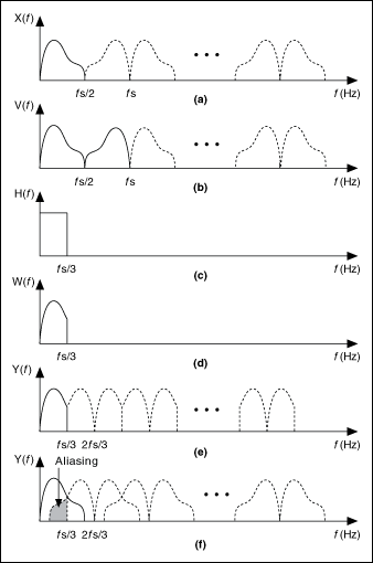
The following figure illustrates the rational resampling of a signal by a factor of 2/3. The different parts in the following figure correspond to the different spectra of the signal at different stages of the rational resampling process, as shown in the previous figure. Because L<M, the lowpass filter has a cutoff frequency of Lfs/(2M) and acts as an anti-aliasing filter. Part (e) of this figure shows the spectrum of the output signal if you use a lowpass filter. You can see that no aliasing occurs. From part (f) of this figure, you can see that if no lowpass filter exists, or if you choose the cutoff frequency of the lowpass filter to be fs/2, aliasing occurs between each spectrum image of the decimated signal. The overlapping spectra indicate aliasing due to the decimation operation.

|
(a) Spectrum of the original signal x(n) |
|
(b) Spectrum of the signal v(n) from directly interpolating the original signal by 2 |
|
(c) Magnitude response of the anti-aliasing filter H(z) |
|
(d) Spectrum of the signal w(n) from the anti-aliasing filter H(z) |
|
(e) Spectrum of the output signal y(n) with the anti-aliasing filter |
|
(f) Spectrum of the output signal y(n) without the anti-aliasing filter |
To design rational resampling filters, use the Rational instance of the DFD MRate Filter Design VI.