Designing Fixed-Point Multirate Filters (Digital Filter Design Toolkit)
The fixed-point multirate filter design process is different from the fixed-point single-rate filter design process. The following figure illustrates a typical fixed-point multirate filter design process. The grey boxes illustrate the floating-point filter design process and the arrows on the left indicate to which steps you can return if the filter design fails to meet the requirements in the current step.
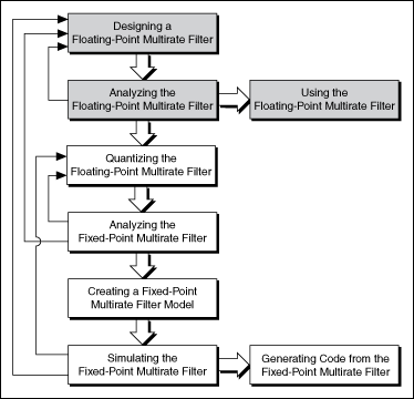
Designing a fixed-point multirate filter involves fewer steps than designing a fixed-point single-rate filter. The following sections describe each step in the fixed-point multirate filter design process and compare the process to the fixed-point single-rate filter design process.
Quantizing Floating-Point Multirate Filters
Use the DFD FXP MRate Quantization VI to quantize floating-point multirate filters. This process is different from quantizing floating-point single-rate filters.
In the fixed-point single-rate filter design process, scaling the filter coefficients is a separate step. However, the fixed-point multirate filter design process integrates this step in the quantization process. Specify an appropriate value in the scale type input of the DFD FXP MRate Quantization VI to scale the multirate filter coefficients.
Depending on which VI you use to quantize the coefficients of a floating-point single-rate filter, you might need to configure some or all of the following items: the gain settings, word length and integer word length, overflow mode, and rounding mode. However, to quantize the coefficients of a floating-point multirate filter, you only need to set the gain processing target and coefficients word length. The DFD FXP MRate Quantization VI automatically calculates the integer word length of the filter coefficients and configures the settings for the overflow and rounding modes. The VI then uses the resulting values to quantize the filter coefficients.
Refer to the MRate_Step3_Analyze Quantized Decimation VI in the labview\examples\Digital Filter Design\Case Studies\Multirate Filter directory for an example that demonstrates how to quantize a floating-point decimation filter and analyze the quantized decimation filter.
 Open example
Analyzing Fixed-Point Multirate Filters
Quantization can cause the characteristics of a fixed-point multirate filter to deviate from the reference floating-point multirate filter. Sometimes quantization even causes the resulting fixed-point multirate filter to fail to meet the target specifications. Therefore, after quantization, you must analyze the behavior of the fixed-point multirate filter. You can use the Multirate Filter Analysis VIs to calculate the frequency response of the fixed-point multirate filter. Based on the frequency response results, you can determine if the fixed-point filter meets the requirements. If the fixed-point filter does not meet the target specifications, try either or both of the following methods:
- Modify the quantization settings for the word length of the coefficients.
- Modify the specifications of the reference floating-point multirate filter to allow larger headroom. A larger headroom helps alleviate fixed-point effects.
To optimize the resulting multirate fixed-point filter, analyze and adjust the filter design iteratively until the frequency response meets the target specifications.
Refer to the MRate_Step3_Analyze Quantized Decimation VI in the labview\examples\Digital Filter Design\Case Studies\Multirate Filter directory for an example that demonstrates how to quantize a floating-point decimation filter and analyze the quantized decimation filter.
Open example
Creating Fixed-Point Multirate Filter Models
When you design a fixed-point multirate filter, fixed-point quantization occurs for the coefficients and for the intermediate operands and results. By using the DFD FXP MRate Modeling VI, you need to configure only the quantizers for the input and output signals. The DFD FXP MRate Modeling VI automatically configures the quantizers for intermediate operands.
Setting the Input and Output Word Lengths
Use the DFD FXP MRate Modeling VI to specify input and output word lengths. These word lengths determine the number of bits to use in representing the input and output signals. For a fixed-point multirate filter, the integer word length of the output signal is the same as that of the input signal.
Setting the Rounding Mode
Fixed-point numbers have limited word lengths, so the available dynamic range of fixed-point numbers is lower than the range available with double-precision and floating-point numbers. Therefore, fixed-point numbers can approximate floating-point numbers only. In the LabVIEW Digital Filter Design Toolkit, the Multirate Fixed-Point Tools VIs use a 32-bit computation for internal operations. Use the output rounding mode input of the DFD FXP MRate Modeling VI to configure the output quantizer.
Setting the Internal Precision
For a multirate filter with a finite impulse response, if both the coefficients word length and input word length are greater than 16 bits, the internal multiplication is equivalent to an I32xI32 operation. Theoretically, you need four I16xI16 multipliers to obtain a full-precision, or I32xI32, result. However, the fixed-point hardware target usually has limited multiplier resources. To conserve the multiplier resources, you can choose the truncation option. This option enables you to use three I16xI16 multipliers to obtain an approximated output. Use the internal precision input of the DFD FXP MRate Modeling VI to choose an appropriate option.
 |
Note A cascaded integrator comb (CIC) filter does not require multipliers, but you also can use this input to set the internal precision for the CIC filter. |
Refer to the MRate_Step4_Model and Simulate FXP Decimation VI in the labview\examples\Digital Filter Design\Case Studies\Multirate Filter directory for an example that demonstrates how to create a fixed-point model of a multirate filter and simulate the filtering result.
Open example
Simulating Fixed-Point Multirate Filters
To determine the quantization and modeling effects on a filtering process, you not only need to analyze the frequency response of a fixed-point filter, but you also need to simulate the filtering process with the actual data. You can use the DFD FXP MRate Simulation VI to simulate the filtering process. To verify if the fixed-point multirate filter works as you expect, compare the simulation result with the actual filtering result that you obtain by processing the same signal with the reference floating-point multirate filter. Ensure that the simulation result matches the actual filtering result. If the simulation result does not match the actual floating-point filtering result, try making the following adjustments:
- Return to the quantization step. Modify the word length for the filter coefficients and the scale type to avoid overflow or underflow.
- Adjust the specifications and redesign the floating-point multirate filter.
Refer to the MRate_Step4_Model and Simulate FXP Decimation VI in the labview\examples\Digital Filter Design\Case Studies\Multirate Filter directory for an example that demonstrates how to create a fixed-point model of a multirate filter and simulate the filtering result.
Open example
Generating Code from Fixed-Point Multirate Filters
After you obtain an appropriate fixed-point filter model, you can implement the resulting fixed-point filter on target hardware. You can export fixed-point integer coefficients from the filter and then use the coefficients in a filter execution engine. You also can generate LabVIEW FPGA code and then use the LabVIEW FPGA Module to target and deploy the resulting FPGA code to an NI Reconfigurable I/O (RIO) target.
Exporting Fixed-Point Integer Coefficients
If you have a filter execution engine for which you need only filter coefficients, you can export the fixed-point multirate filter coefficients to a text file using the DFD Save MRate to Text File VI. You can save the multirate filter coefficients to a text file and load them to the execution target. The text file contains a section that provides all information about the fixed-point integer coefficients and corresponding quantizers.
Refer to the Export Multirate FIR Coef to Xilinx COE File VI in the labview\examples\Digital Filter Design\Fixed-Point Filters\Multirate directory for an example that demonstrates how to export fixed-point integer coefficients.
Open example
Generating LabVIEW FPGA Code
You can use the DFD FXP MRate Code Generator VI to generate LabVIEW field-programmable gate array (FPGA) code from a multirate filter.
|
Note To generate LabVIEW FPGA code, you must install the LabVIEW FPGA Module and NI-RIO driver software with R Series support. To execute the FPGA code, you also need an FPGA target on which to run the code. |
The Digital Filter Design Toolkit uses LabVIEW projects to manage the resulting LabVIEW FPGA code. The following figure shows an example project file that contains LabVIEW FPGA code.
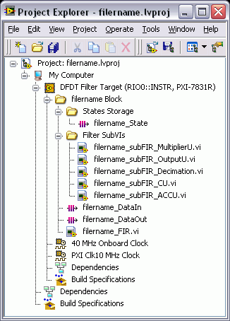
In the previous figure, the filtername.lvproj file, where filtername denotes the name of the fixed-point filter, contains the following folders and VIs in addition to the default items.
- filtername Block—This folder contains all generated VIs and subVIs related to the fixed-point filter from which you generate LabVIEW FPGA code. You can apply the filter to another project by copying and pasting this folder into the target project file.
Note Each filter block contains some FPGA memory components to store the internal states of the fixed-point multirate filter. Multiple filter blocks cannot share the same memory components in one FPGA project. Therefore, if you want to use the filter block multiple times in one FPGA project, you must generate the filter blocks with different filter names from the same fixed-point multirate filter. - States Storage—This folder contains information about the specific resources on an FPGA target, including FIFOs and memory items. These resources store the internal states of the fixed-point filter. You usually do not need to modify the items in this folder.
- Filter SubVIs—This folder contains the generated subVIs. You usually do not need to modify these subVIs.
- filtername_DataIn—This item defines the input FIFO channel to the filter block of a fixed-point multirate filter. The fixed-point multirate filter uses the FIFO to communicate with other sections of the FPGA code, such as the FPGA I/O Node.
- filtername_DataOut—This item defines the output FIFO channel from the filter block of a fixed-point multirate filter. If you want to return the filtered signal directly to a host machine, you can modify the property of this file by completing the following steps:
- Right-click filtername_DataOut.
- Choose Properties from the shortcut menu.
- Choose Target to Host-DMA from the Type menu.
- Click OK.
- filtername_FIR.vi—This VI is the top-level VI of the generated LabVIEW FPGA code. To use the LabVIEW FPGA code, drag and drop this VI to the block diagram of the calling VI.
The way you use LabVIEW FPGA code is different from the way you use a general LabVIEW VI. The following figure shows an example of a block diagram that uses LabVIEW FPGA code generated from the filtername_FIR VI.
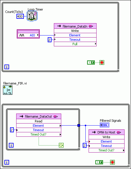
In the previous figure, the filtername_FIR VI is not connected to any other items on the block diagram. However, this VI actually communicates with the items in the loop structures by processing the input signal from the filtername_DataIn FIFO and returning the output signal to the filtername_DataOut FIFO.
You can generate LabVIEW FPGA code from a fixed-point single-stage multirate filter by using the DFD FXP MRate Code Generator VI. Refer to the MRateDecimation.lvproj file in the labview\examples\Digital Filter Design\Case Studies\Multirate Filter directory for an example that demonstrates how to generate LabVIEW FPGA code from a fixed-point single-stage decimation filter.
Open example
You also can generate LabVIEW FPGA code from a fixed-point multistage multirate filter by using the DFD FXP NStage MRate Code Generator VI. Refer to the NStageMRateDecimation.lvproj file in the labview\examples\Digital Filter Design\Case Studies\Multistage Multirate Filter\NStageMRate directory for an example that demonstrates how to generate LabVIEW FPGA code from a fixed-point multistage multirate filter.
Open example
Postprocessing Filtered Signals
After you deploy fixed-point filter coefficients to the target hardware, you can postprocess the filtered signal using the DFD FXP MRate Postprocessing VI. Refer to the MRate_Step6_Postprocessing VI in the labview\examples\Digital Filter Design\Case Studies\Multirate Filter directory for an example that demonstrates how to postprocessing a filtered signal.
Open example