Minimum and Maximum Phase FIR Design (Digital Filter Design Toolkit)
The Designing Special Filters book discusses linear phase finite impulse response (FIR) filter designs, which are actually amplitude approximations that use the following complex approximation criterion:

where D(ωi) is the ideal frequency response, H(ωi) is the frequency response of the designed filter, and W(i) is the positive weight at the ith frequency point.
Many applications require linear phase to ensure that the frequency components of an input signal pass through the filter with the same delay. If you have an application that does not require linear phase, you can control the magnitude response of the filter and allow the filtering process to change the delay relationship between different frequency components arbitrarily. You can use the following expression for this type of magnitude approximation problem.

Without the phase constraint, you can achieve the same approximation error magnitude with a lower filter order or a smaller approximation error magnitude with the same filter order. Both options reduce the implementation cost.
More than one set of filter coefficients can have the same magnitude response. In the z-plane you can create a new set of coefficients with the same magnitude response, unless all zeroes are on the unit circle, through the allpass transformation of flipping zeroes to their conjugate reciprocal locations relative to the unit circle. You can specify minimum phase or maximum phase to eliminate the ambiguity about which set of FIR filter coefficients you are using.
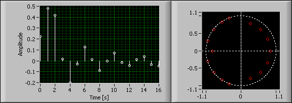
All zeroes in a minimum phase FIR filter are inside or on the unit circle. Minimum phase filters sometimes are called minimum energy delay filters because the energy of the impulse response is maximally concentrated toward the beginning of the impulse response.
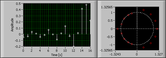
All zeroes in a maximum phase FIR filter are outside or on the unit circle. The energy of the impulse response is maximally concentrated toward the end of the impulse response. Given a certain magnitude response, the impulse responses of the minimum and the maximum phase FIR filters are time-reversed.
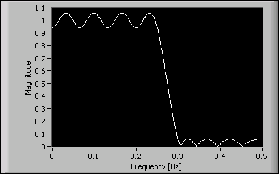
The following figure shows the magnitude response of a 16th order FIR filter.

You can use two different sets of filter coefficients to match the magnitude response of the FIR filter. The following figure shows the impulse response and zeroes of a minimum phase filter with the same magnitude response of the 16th order FIR filter.

The following figure shows the impulse response and zeroes of a maximum phase filter with the same magnitude response of the 16th order FIR filter.

Minimum phase filters are especially useful in control applications. A filtering process in a control loop typically requires the response to an input stimulus to be as quick as possible. A large delay in the filtering process can cause a negative feedback control loop to become unstable.
One disadvantage of linear phase FIR filters is that the system delay, also called the group delay, is fixed to half the filter order, which might be unacceptably long when the filter order is large. Use minimum phase filters in situations where minimizing delay is critical unless the system requires a linear phase filter or the linear phase filter order is relatively small.
You can design minimum or maximum phase FIR filters using the DFD Remez Design VI. Set the filter type input to Minimum Phase or Maximum Phase and the remaining specifications just as you design a linear phase filter. Refer to the Exact Gain Control Design and Ripple Constraint Design topics for information about designing minimum and maximum phase filters with exact gain control or ripple constraints.
You can create a minimum phase filter by designing a linear phase filter and converting it to a minimum phase filter by flipping the zeroes that are outside the unit circle to their conjugate reciprocal position inside the unit circle. Although the new minimum phase filter possesses the same magnitude response as the original linear phase filter, the new filter is not optimal relative to the filter magnitude specification. You can achieve a closer match to the magnitude specification or a lower filter order by specifying a minimum phase filter directly.
 |
Note Minimum phase filters can achieve better results in terms of a lower ripple or lower order for a given magnitude specification than equivalent linear phase filters. Therefore, minimum phase can be a better choice than linear phase in applications where the phase response is not constrained. |