Interpolation (Digital Filter Design Toolkit)
Interpolation is the process of increasing the sampling frequency of a signal to a higher sampling frequency that differs from the original frequency by an integer value. Interpolation also is known as up-sampling. The spectrum of the output signal ideally is the same as the input signal spectrum, except the output signal spectrum contains an additional high-frequency region with zero-power density.
The following figure shows a typical L-fold interpolation filter, where L is the target integer increase in the sampling frequency.

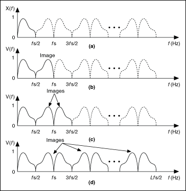
The interpolation filter contains an L-fold expander followed by a lowpass FIR filter H(z). The L-fold expander inserts L−1 zeroes between consecutive samples to the original signal x(n) and changes the sampling frequency fs of the original signal x(n) to a new sampling frequency Lfs. This process introduces images, as shown in the figure below, to the original signal. The interpolation filter then uses the lowpass FIR filter H(z) to remove the images. Therefore, this lowpass FIR filter is an anti-imaging filter. The interpolation filter then returns an output signal y(n) with the new sampling frequency.
 |
Note The Multirate Processing VIs use a polyphase implementation, which is more efficient than the procedure in the previous figure, to implement interpolation. Refer to the book Multirate Systems and Filter Banks for more information about polyphase implementations. Interpolation filters that use a polyphase implementation compute only the nonzero input samples, not the inserted zero samples, thus reducing the computational complexity of the filters. |
The following figure shows the spectrum of the original signal x(n) and the spectra from directly interpolating the signal by 2, 3, and L without using an anti-imaging filter. Notice multiple images emerge in the range from 0 to half of the resulting sampling frequency in parts (b), (c), and (d) of the figure. These images demonstrate the effect of interpolation.

|
(a) Spectrum of the original signal x(n) |
|
(b) Spectrum of the signal v(n), interpolated by a factor of 2 |
|
(c) Spectrum of the signal v(n), interpolated by a factor of 3 |
|
(d) Spectrum of the signal v(n), interpolated by a factor of L |
The interpolation system uses the lowpass filter H(z) after the expander to attenuate the frequency components of the signal from fs/2 to Lfs/2. In the time domain, the effect of H(z) is to replace the inserted zero value samples that the expander introduces with the interpolated values. When replacing the inserted zeroes with interpolated values, the anti-imaging lowpass filter H(z) might alter the original values. Use a Nyquist interpolation filter for H(z) to maintain the original values.
To design interpolation filters, use the Multirate Filter Design VIs with the filtering mode input set to Interpolation.