Linear Phase Filters (Digital Filter Design Toolkit)
Linear phase digital filters allow all the frequency components of an input signal to pass through the filter with the same delay, which means that the group delay through the filter is a constant value independent of the frequency. Linear phase filters are useful in filtering applications in which you want to minimize signal distortion and spreading over time.
Nonlinear phase response, or dispersion, can be harmless in audio and other applications in which mild phase distortion is often imperceptible to humans. However, phase distortion can be harmful in some applications. For example, in digital communications applications, signal spreading caused by phase distortion can cause interference between time concentrated information symbols.
A minimum phase filter is a type of nonlinear phase filter that optimally minimizes the group delay at all frequencies for a given magnitude response at the expense of phase distortion. Minimum phase filters can be useful in control applications in which minimizing delay is more important than minimizing signal spreading.
Mathematical Definition
The digital filter frequency response H(f) is expressed in terms of magnitude and phase in the following equation:
| H(f) = |H(f)|ejφ(f) | (A) |
where |H(f)| and φ(f) are both real-valued functions of frequency f and represent the magnitude and phase of the frequency response.
Only finite impulse response (FIR) filters can have exactly linear phase. You can design linear phase FIR filters using either window-based design methods or the Remez design method. The Remez design method in the DFD Remez Design VI is more powerful and flexible than window-based design methods.
The equation above reduces to the following equation for a linear phase FIR digital filter.
| H(f) = (j)m A(f)e−jπNf | (B) |
| where | m = 0, 1 |
| A(f) is the amplitude response of the filter | |
| N is the order of the filter, which is equal to the number of filter taps minus one | |
| f is the normalized frequency with the range [0, 0.5] | |
| If the filter coefficients h(n) (where n = 0, 1, .., N) are symmetric, h(n) = h(N−n), and m must be 0 | |
| If the filter coefficients h(n) are antisymmetric, h(n) = −h(N−n), and m must be 1 |
Types of Linear Phase FIR Filters
The following table lists the four types of linear phase FIR filters and the characteristics of each type. The book Digital Filter Design contains more information about linear phase FIR filters.
| Type | Classification | Frequency Characteristics |
|---|---|---|
| I | Even-order, symmetric | A(f) is symmetric about f = 0 and f = 0.5 A(f) is periodic with period 1 |
| II | Odd-order, symmetric | A(f) is symmetric about f = 0 and antisymmetric about f = 0.5 A(f) is constrained to 0 at f = 0.5 A(f) is periodic with period 2 |
| III | Even-order, antisymmetric | A(f) is antisymmetric about f = 0 and f = 0.5 A(f) is constrained to 0 at both f = 0 and f = 0.5 A(f) is periodic with period 1 |
| IV | Odd-order, antisymmetric | A(f) is antisymmetric about f = 0 and symmetric about f = 0.5 A(f) is constrained to 0 at f = 0 A(f) is periodic with period 2 |
Use the DFD Remez Design VI to design linear phase FIR filters. Set the order input and the filter type input according to the Classification column of the table above. The DFD Remez Design VI designs the appropriate type of linear phase FIR filter based on the two inputs.
Use the following guidelines to determine the type of linear phase FIR filter you design.
- Type III and IV cannot be lowpass-like filters.
- Type II and III cannot be highpass-like filters.
- Type III and IV work well for differentiators or Hilbert transformers because they can give a constant 90° phase shift.
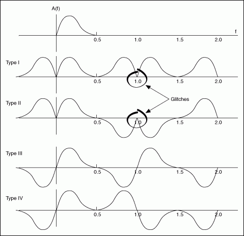
Experiment with different types. More than one type might produce an acceptable result for some target filter responses, but only one type can meet the target specifications. Select the filter type that has the smoothest frequency response. For example, the following figure illustrates the types of frequency response symmetry for each type of linear phase FIR filter, assuming a sampling frequency of fs = 1. Notice that in this example, a Type I or Type II filter has glitches, or rapid changes, at the frequency point of 1. A Type III or Type IV filter yields the smoothest frequency response because they do not contain glitches.

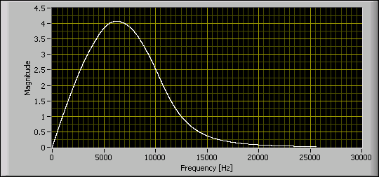
The following figure shows the magnitude response requirement of an ITU-468-weighting filter. Notice that the magnitude response is zero at DC and small but nonzero at high frequencies. Therefore, Type IV (odd order, antisymmetric) is the best choice for approximating this response.
