Cascaded Integrator Comb (CIC) Filters (Digital Filter Design Toolkit)
From LabVIEW Digital Filter Design Toolkit
Cascaded Integrator Comb (CIC) Filters (Digital Filter Design Toolkit)
A CIC filter is a special class of linear phase, finite impulse response (FIR) filter. CIC filters do not require multipliers and use a limited amount of storage. Therefore, CIC filters are more efficient than conventional FIR filters, especially in fixed-point applications. You usually use CIC filters in multirate systems with large sampling frequency conversion factors, such as digital down converters (DDC) and digital up converters (DUC) in communication systems.
CIC Filter Basics
CIC filters do not have multipliers and consist of only adders, subtracters, and registers. Therefore, you can implement multirate filters efficiently using the CIC filter structure. CIC filters are defined by the following transfer function:
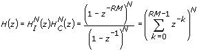
| where | z is a complex variable |
| I is a basic integrator section | |
| C is a basic comb section | |
| M is the sampling frequency conversion factor | |
| R is the differential delay | |
| N is the number of stages |
Theoretically, R and N can be any positive integer value, but the LabVIEW Digital Filter Design Toolkit constrains R to be either 1 or 2 because you do not need to use other values in most cases. N is in the range [1, 8]. The equation above shows that a CIC filter is equivalent to N stages of cascaded FIR filters with unit coefficients. Each FIR filter has a rectangular impulse response. All coefficients of the FIR filters are 1 and therefore symmetric, so the CIC filter has a linear phase response and constant group delay.
Use the Multirate CIC Design Express VI to design a CIC filter. Refer to the CIC Filter Design VI in the labview\examples\Digital Filter Design\Floating-Point Filters\Multirate directory for an example that demonstrates how to use the Multirate CIC Design Express VI to design a CIC filter.
![]() Open example
Open example
Implementing Fixed-Point CIC Filters
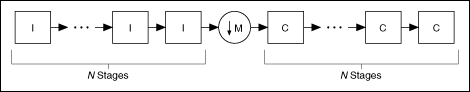
The Digital Filter Design Toolkit supports fixed-point implementation of only lowpass CIC filters. To implement fixed-point CIC filters, cascade N basic integrator sections (the I block) and N basic comb sections (the C block) together with a sampling frequency conversion factor. The following figure shows an example of a fixed-point implementation of an N-stage decimation CIC filter, where M is the sampling frequency conversion factor.
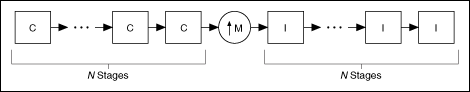
The following figure shows an example of a fixed-point implementation of an N-stage interpolation CIC filter.
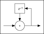
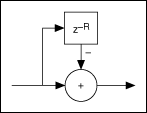
The following figure shows a basic integrator section in detail.
The following figure shows a basic comb section in detail.
Setting the Internal Precision
In a fixed-point implementation, the maximum bit width required for a CIC decimation filter is the sum of the input bits and the bits that the filter uses in accommodating the maximum filter gain. Using the maximum bit width for each integrator or comb section guarantees that no overflow occurs at the output of the filter. The maximum bit width also ensures that you obtain a full-precision result. However, obtaining the full-precision result requires the maximum field-programmable gate array (FPGA) hardware resources.
In most real-world applications, the required output bit width is smaller than the maximum bit width. Therefore, you can discard the least significant bits (LSBs) from the maximum bit width to obtain a smaller output bit width. Using the DFD FXP MRate Modeling VI, you can prune the LSBs in each successive integrator or comb section. This operation is known as bit pruning. Bit pruning enables you to obtain a precision that approximates the full precision and to spare the FPGA hardware resources. However, bit pruning introduces additional noise to each processing section, and the amount of LSBs that you discard determines the noise level.
When using the DFD FXP MRate Modeling VI to model a fixed-point CIC filter, you can set the internal precision input to Truncated to prune the intermediate bit widths. This option is valid for only multirate FIR filters and fixed-point CIC decimation filters. If you set internal precision to Full, this VI applies the maximum bit width to each processing section.
The following figure shows an example of filtering results by using both the Truncated and Full options.
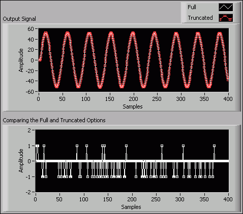
In the Output Signal graph of the previous figure, you can see that the Truncated plot renders nearly the same filtering result as the Full plot does. The Comparing the Full and Truncated Options graph shows the detailed difference between the two filtering results. The few nonzero values indicate the slight precision difference between the two internal precision options.