Decimation (Digital Filter Design Toolkit)
Decimation is the process of reducing the sampling frequency of a signal to a lower sampling frequency that differs from the original frequency by an integer value. Decimation also is known as down-sampling. The lowpass filtering associated with decimation removes high-frequency content from the signal to accommodate the new sampling frequency.
Decimation is useful in applications in which the Nyquist frequency of a signal is much higher than the highest frequency of the signal. Decimation filters help you remove the excess bandwidth and reduce the sampling frequency of the signal. Decimation filters also help you reduce the computational resources required for processing and storing the signal. During the analog-to-digital (A/D) conversion process, decimation filters also can reduce the variance of quantization noise in a signal and maintain the signal power, thus improving the signal-to-noise ratio (SNR).
The following figure shows a typical M-fold decimation filter, where M is the integer value by which you want to decrease the sampling frequency. This filter contains a lowpass FIR filter H(z). This lowpass FIR filter is an anti-aliasing filter followed by an M-fold decimator. The decimator passes every Mth sample and discards the other samples. After this operation, the decimation filter changes the sampling frequency fs of the input signal x(n) to a new sampling frequency fs/M. The decimation filter then returns an output signal y(n) with the new sampling frequency.

To prevent aliasing, this system uses the lowpass filter H(z) before the M-fold decimator to suppress the frequency contents above the frequency fs/(2M), which is the Nyquist frequency of the output signal. This system produces the same results as an analog anti-aliasing filter with a cutoff frequency of fs/(2M) followed by an analog-to-digital (A/D) converter with a sampling frequency of fs/M. Because the system shown in the figure above is in the digital domain, H(z) is a digital anti-aliasing filter.
 |
Note The Multirate Processing VIs use a polyphase implementation, which is more efficient than the procedure in the previous figure, to implement decimation. Refer to the book Multirate Systems and Filter Banks for more information about polyphase implementations. Decimation filters that use a polyphase implementation compute only the final expected output samples, not the samples to discard, thus reducing the computational complexity of the filters. |
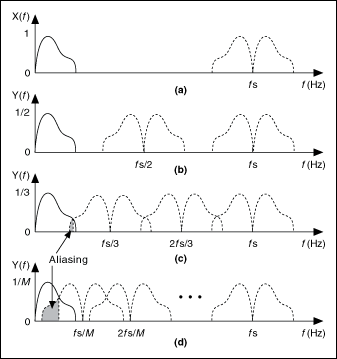
The following figure illustrates the potentially harmful effects of not using an anti-aliasing filter before the decimator. This figure shows the spectrum of the original signal x(n) and the spectra of the signals resulting from decimating the original signal by 2, 3, and M. Notice the overlapping spectra in parts (c) and (d) of the figure. The overlapping spectra indicate aliasing due to the decimation operation.

|
(a) Spectrum of the original signal x(n) |
|
(b) Spectrum of the output signal y(n), decimated by a factor of 2 |
|
(c) Spectrum of the output signal y(n), decimated by a factor of 3 |
|
(d) Spectrum of the output signal y(n), decimated by a factor of M |
To design decimation filters, use the Multirate Filter Design VIs with the filtering mode input set to Decimation.