Understanding Filter Structure Graphs (Digital Filter Design Toolkit)
From LabVIEW Digital Filter Design Toolkit
Understanding Filter Structure Graphs (Digital Filter Design Toolkit)
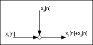
The realization of a digital filter involves summations and multiplications of the output, input, and intermediate operands. You must make the values that pass along the signal path available during the realization process. Therefore, to represent the structure of a filter using a signal flow graph, you not only need adders and multipliers, but you also need delays that help you store the passed values. The following figure shows the symbol of an adder.
You can treat a consecutive sequence of adders in a filter structure as an accumulator.
The following figure shows the symbol of a multiplier.
![]()
The following figure shows the symbol of a delay.
![]()
In the previous figure, z–1 is a delay that stores the value of x[n]. The z-transform of x[n–1] is z–1 times the z-transform of x[n]. The number of adders and multipliers implies computational complexity in the realization of a filter structure, and the number of delays implies memory unit requirements in the hardware. The more adders, multipliers, and delays a filter structure contains, the more computational complexity and memory units the filter requires. You can view the signal flow graphs of the following filter structures: