Designing Floating-Point Multirate Filters (Digital Filter Design Toolkit)
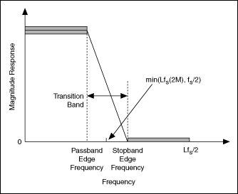
You can follow the floating-point single-rate filter design process to design a floating-point multirate filter. This topic explains how to use the Multirate FIR Design Express VI to design a lowpass multirate finite impulse response (FIR) filter. The following figure illustrates the typical magnitude response of a lowpass filter in multirate systems.

In this figure, fs denotes the sampling frequency of the input signal. When designing filter specifications, you must take the filtering mode into consideration. Because decimation and interpolation are special cases of rational resampling, you can use the following filter specifications to design any filter with a rational factor of L/M.
| Filter Specification | Value Range |
|---|---|
| Passband edge frequency | 0 < fpass < min(Lfs/2M, fs/2) |
| Stopband edge frequency | fpass < fstop < Lfs/M−fpass |
Typically, fpass is the highest frequency of interest in the input signal. If fstop < min(Lfs/(2M), fs/2), the transition band is free of aliases. If you change the constraints of fstop to min(Lfs/(2M), fs/2) < fstop < (Lfs/2M−fpass), the filter has a wider transition band and a lower order, which can reduce the computational complexity significantly in filtering operations. However, the transition band then contains aliasing in the frequency conversions.
Entering Floating-Point Filter Specifications
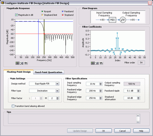
After you place the Multirate FIR Design Express VI on the block diagram, the Configure Multirate Filter Design dialog box appears, as shown in the following figure:

On the Floating-Point Design tab of the configuration dialog box, you can select the filter type and design method from the pull-down menus and specify the filter factor. You then can enter the filter specifications through either the numeric controls on the right side of the tab or the magnitude response graphical interface on the configuration dialog box. The results are equivalent.
Using the Numerical Controls
Similar to the numerical controls for single-rate filter design, the numerical controls for multirate filter design also contain frequency ranges and ripple constraint settings. In addition to these settings, you also need to specify the sampling frequency of the input signal in the Input sampling frequency numeric control. This VI then automatically calculates the sampling frequency of the output signal based on the filter specifications you entered.
Using the Graphical Interface
The Magnitude Response graph displays the magnitude response of the designed multirate filter. The magnitude axis can be either a linear or a logarithmic scale. Remove the checkmark from the Magnitude in dB checkbox to use a linear scale, or keep the checkmark in the Magnitude in dB checkbox to use a logarithmic scale.
The Magnitude Response graph contains a set of cursors that you can use to specify the passband and stopband. Use the passband and stopband cursors to change the passband and stopband, respectively, of the multirate filter. Under the linear scale, the distance between unity and the horizontal passband cursor specifies the maximum passband ripple. The location of the vertical passband cursor indicates the passband edge frequency. The stopband cursors work the same when defining the specifications of the stopband. Under the logarithmic scale, the distance between 0 dB and the horizontal stopband cursor specifies the stopband attenuation.
Guidelines for Entering Filter Specifications
As you define a filter specification, you must adhere to a set of rules to maintain valid specifications. If you do not adhere to the following rules, the Configure Multirate Filter Design dialog box displays a message in the Tips indicator with suggestions for repositioning the cursors.
- Keep the horizontal cursors in the range (0, 1) in a linear scale or (−inf, 0 dB) in a logarithmic scale.
- Keep the horizontal passband cursor above the horizontal stopband cursor.
- The Passband edge frequency value must be less than the Nyquist frequency, or you must keep the vertical passband cursor to the left of the Nyquist cursor.
- The Stopband edge frequency value must be greater than the Passband edge frequency value, or you must keep the vertical passband cursor to the left of the stopband cursor.
- If you remove the checkmark from the Transition band aliasing allowed checkbox to avoid aliasing in the transition band, keep the Stopband edge frequency value between the Passband edge frequency value and the Nyquist frequency, or keep the vertical stopband cursor between the vertical passband and Nyquist cursors. If you keep the checkmark in the Transition band aliasing allowed checkbox to allow aliasing in the transition band, keep the vertical stopband cursor between the vertical passband cursor and the vertical stopband limit cursor.
After you finish entering the filter specifications, click the Update Design button to apply the new specifications.
Refer to the MRate_Step1_Design Decimation VI in the labview\examples\Digital Filter Design\Case Studies\Multirate Filter directory for an example that demonstrates how to use the Multirate FIR Design Express VI to design a decimation filter.
Analyzing the Floating-Point Filter Design
When you design the multirate filter using the Multirate FIR Design Express VI, you can analyze the filter design by examining the magnitude response and filter order in real time.
Using Floating-Point Multirate Filters
After you analyze the filter design, you can either use the multirate filter to process an input signal or quantize the filter coefficients of the multirate filter. Use the Multirate Processing VIs to process a signal with the multirate filter you designed. The Multirate Processing VIs can process an input signal in the following three ways:
- As a single block of data
- As a sequence of data blocks
- As a sequence of data blocks with saved internal filter states
Use the DFD MRate Filtering for Single Block VI or the DFD NStage MRate Filtering for Single Block VI to process a single block of data. When processing a single block, the VIs extend the input signal block at both ends to ensure the output signal block has the same length as the input signal block. Use the other Multirate Processing VIs to process multiple signal blocks continuously. These VIs automatically retain the internal states of the filter between blocks, and they allow you to save and restore filter states without causing artifact glitches in the processed data.
You achieve the same results when you process multiple blocks as a sequence of blocks as when you process them together as one single block. To eliminate the delay between the input and output signals, enable the zero-phase filtering option when using the Multirate Processing VIs.
Refer to the MRate_Step2_Perform Decimation Filtering VI in the labview\examples\Digital Filter Design\Case Studies\Multirate Filter directory for an example that demonstrates how to use a decimation filter in a filtering application.
Quantizing Multirate Filter Coefficients
After you analyze the filter design, you can either quantize the filter coefficients of the designed multirate filter and convert the floating-point filter into a fixed-point filter or use the floating-point multirate filter to process an input signal. To quantize the filter coefficients, place a checkmark in the Quantize filter checkbox on the Fixed-Point Quantization tab, and specify the coefficients word length, coefficients scale type, and gain settings.
