Arbitrary Shape Filters (Digital Filter Design Toolkit)
If you want to design a linear phase finite impulse response (FIR) filter with an arbitrary magnitude response, you can use the DFD Remez Design VI. If you want to design a filter in which linear phase is not required but minimizing filter order is important, you can use the DFD Least Pth Norm Design VI to design an infinite impulse response (IIR) filter.
You can describe an arbitrary frequency response with multiple points using piecewise linear interpolation. The number of points you must supply to describe the shape depends on the target arbitrary shape magnitude response in a certain frequency band. You do not have to space the points evenly. Use more points where the magnitude response is tightly curved and fewer points where the magnitude response is more linear.
FIR Filters with Arbitrary Magnitude Responses
To design a linear phase FIR filter with an arbitrary shape magnitude response, use the DFD Remez Design VI and set the filter type input to Symmetric or Antisymmetric according to the linear phase FIR filter type table. Then describe the shape of the filter by specifying multiple points in the band specs input.
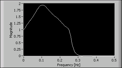
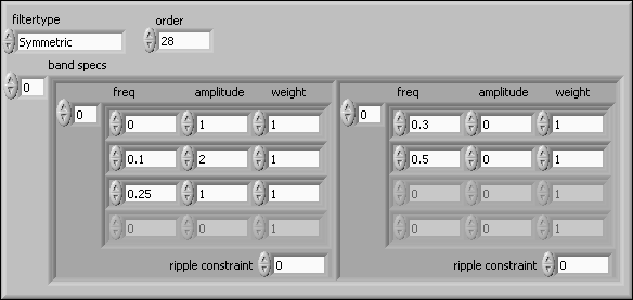
The following example uses a lowpass filter with a passband frequency ranging from 0 to 0.25 and a stopband frequency ranging from 0.3 to 0.5. Three points at frequencies 0, 0.1, and 0.25 with expected amplitudes of 1, 2, and 1, respectively, describe the shape of the passband range. To design this filter, enter the specifications shown in the following figure into the DFD Remez Design VI.
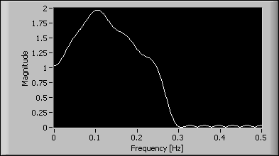
The following figure shows the magnitude response of the designed filter.
The previous example describes the passband shape with only three points. You also can describe an arbitrary passband shape with as many points as necessary. The following example uses 5,000 evenly-shaped frequency points to describe the passband shape of a sinc compensation lowpass filter. You can use this sinc compensator to correct the amplitude droop caused by a zero-order hold in a digital-to-analog (D/A) converter, as shown in the following figure:
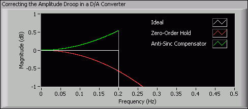
An amplitude droop measures the amount that the signal power decreases in a specified frequency range. In the previous figure, the Zero-Order Hold plot shows the magnitude response of a zero-order hold in the D/A converter. You can see an amplitude droop exists in the frequency range of interest [0, 0.2]. To correct the amplitude droop, you can create a filter that whose magnitude response is similar to the Anti-Sinc Compensator plot in the frequency range of interest [0, 0.2]. You can create the filter by describing the passband shape with the corresponding inverse sinc function values of the droop. The following figure shows the magnitude response of the designed filter.
IIR Filters with Arbitrary Magnitude Responses
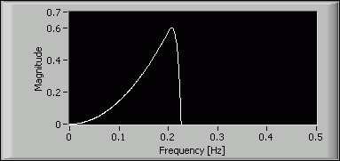
If you want to design an IIR filter with an arbitrary shape magnitude response and the phase response is not important, use the DFD Least Pth Norm Design VI and set the filter type input to either Minimum Phase or Maximum Phase. The DFD Least Pth Norm Design VI ignores all other phase specification inputs, including group delay and phase in the band specs input. Define the shape of the magnitude response by entering multiple points in the band specs input.
For example, you can design a minimum phase IIR filter with the same arbitrary magnitude response as the previous example. Set the filter type input to Minimum Phase and enter the same band specs into the DFD Least Pth Norm Design VI. The following figure shows the magnitude response of the designed filter.
