Current & Voltage Readout
From WinFluor
Recording > Signals Monitor (Seal Test) > Current & Voltage Readout
A readout of the cell membrane holding current and voltage, and test pulse amplitude, appears at the bottom of the monitor window.
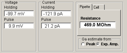
During initial formation of a giga-seal, the Pipette option displays pipette resistance, computed from
![]()
where Vpulse and Ipulse are the steady-state voltage and current pulse amplitudes.
The Cell option displays the cell membrane conductance, Gm, capacity, Cm, and access conductance, Ga,
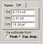
computed from
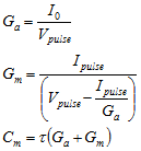
where I0 is the initial current at the peak of the capacity transient and is the exponential time constant of decay of the capacitance current (See Gillis, 1995, for details). Note. If Ga, Gm and Cm are to be estimated correctly, the patch clamp’s pipette series resistance compensation and capacity current cancellation features must be turned off.
A good test, to check if WinFluor is set up with the correct input/output connections and channel scaling factors, is to attach the model cell supplied with most voltage/patch clamps, and observe the holding potential and current, test pulse amplitude and cell parameters correspond with the known values of the model.