Analog Inputs & Amplifier Settings
From WinFluor
Getting Started > Analog Inputs & Amplifier Settings
To set up WinFluor to use an attached patch clamp or other analogue inputs, select
Setup->Camera/System Setup
to display the Camera/System Setup dialog box then choose the Analog Inputs & Amplifiers page.
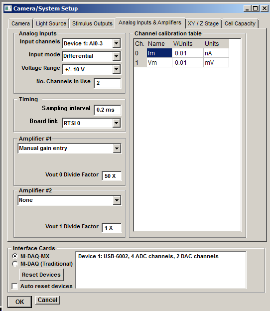
Input Channels
Select the range of analogue input channels to be used for analogue input from the Input Channels list.
Analog Input mode
The A/D input mode for the interface device is selected from the Input mode list. Analogue input channels can be configured to operate in either differential or single-ended input mode. In differential mode, the input signals are derived from the differences between pairs of inputs (AI0 – AI8, AI1 – AI9, etc.) In single-ended mode, the signals are derived from AI0 .. AI7 alone, measured relative the AISENSE input.
The A/D Input mode setting must match the type of National Instruments input/output box used to connect signals to the interface board. The default setting is Differential and this is the only setting that can be used with the BNC-2110 input/output panel or USB-6229-BNC device. Note. If a BNC 2090 19" rack mountable I/O panel is in use and Differential mode is selected, ensure that all SE/DI switches are set to DI. (If Single-Ended mode is selected, with a BNC-2090 panel, ensure that the SE/DI switches are set to DI and the NRSE/RSE switch to RSE.)
No. channels
Set the number of analogue input channels to be acquired in the No. channels In Use box (typically 2 channels, cell membrane current and voltage). The number of channels can be increased (max. 8 channels) if additional analogue signals are connected.
Sampling Interval
Set the analogue sampling interval in the Sampling interval box (default = 0.1 ms). (Note that setting the sampling interval here changes the master clock timing resolution which defines the precision of image capture timing and waveform generation.)
Voltage Range
Select the input voltage range of the analogue-digital converter from the Voltage Range list (default = 10V). In order to get an accurate measure of the amplitude of an analogue signal it is important to ensure that it spans a significant proportion (30-50%) of the A/D converter's input voltage range. By changing the voltage range you can adapt the sensitivity of the A/D converter to best match the amplitude of the signals from your experiment.
Amplifier
WinFluor supports up to two patch clamp amplifiers. Select the type of the first attached patch clamp amplifier from the Amplifier #1 list.
If the amplifier provides gain and/or mode telegraph signals, check that the gain and mode telegraph outputs are connected to the analogue input channels specified in the Gain Tel. and Mode Tel. boxes. Typically the gain telegraph output is connected to analogue input 7 and the mode telegraph to input 6. (Note. Not all amplifiers require telegraph channels, either because they do not support telegraphs or transfer the telegraph data via USB or serial connections).
The command voltage signals for Amplifiers #1 is provided by analogue stimulus channel Vout 0. Check that the analogue output channel associated with Vout 0 is connected to the command voltage input of the patch clamp. The Vout 0 Divide Factor (the scaling factor between the applied command voltage and resulting cell membrane potential set by the patch clamp) is set automatically when the amplifier type is selected.
If a second patch clamp is available, enter its settings in the Amplifier #2 group.
Manual patch clamp settings
If the patch clamp amplifier is not one supported by WinFluor or if it does not have a gain telegraph facility, then the calibration factors for the current and voltage analogue channels must be entered manually. To do this, select Manual Gain Entry in the Amplifier list and enter the appropriate calibration information into the channel calibration table. The Channel calibration table contains the name, units and calibration factor for each analogue input channel used by WinFluor. There are 3 entries in the table for each analogue channel.
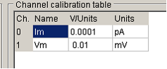
Names contains a 1-4 letter name used to identify the source of the channel (e.g. Vm, Im).
Units defines the measurement units of the signal (e.g. mV, pA etc.).
V/Units defines the scaling factors relating the voltage level at the inputs of the A/D converter (in V) to the actual signal levels in each channel (in the channel units).
For instance, if the membrane voltage output of your patch clamp supplies a signal which is 10X the measured membrane potential of the cell, and the units have been defined as mV, then the appropriate V/Units setting is 0.01 (since the patch clamp voltage output is 0.01 Volts per mV)
In the case of patch clamp current channels, the V/Units value is determined by the current gain setting which is usually a switchable value, e.g. if the current output was set at 0.5 mV/pA, and the channel units were pA, the V/Units settings would be 0.0005.)
The patch clamp command voltage divide factor (the scaling factor between the applied command voltage and resulting cell membrane potential) Enter the division factor in the Vout 0 Divide Factor box. (Typical divide factors are 50 (Axon Instruments amplifiers) or 10 (Heka EPC-7/8).)
Master Clock Timing
To set the timing resolution of the master clock used for cameras, light source and analogue input and output synchronisation, enter a time interval into the Timing resolution box. (The default value is 0.1 ms).
If two or more interface cards are installed in the system and connected together internally using National Instruments RTSI bus cables, select RSTI 0 as the Clock synch. link option. If cards are linked externally using the PFI5 line, select the PFI 5 option. (Note. The PFI 5 option currently only works NIDAQ (Traditional) library option. Synchronisation using the RTSI bus is to be preferred.)