


| < 第43课 | 第45课 > |
第44课 |
 |
 |
 |
 |
|
 |
 |
 |
 |
| 大家好,欢迎来到新的一课,在这一课中我们将扩展glCamera类,来实现镜头光晕的效果。在日常生活中,当我们对着光源看时,会发现强烈的反光。 为了完成这个效果,我们需要一些数学知识。首先,我们需要一些函数,用来检测某个点或球是否在当前的视景体内。接着我们需要一些纹理作为我们的光晕效果,我们可以把它贴在显示面上。 在我的上一个摄像机类里把下面函数写错了,现在修正如下: |
void glCamera::SetPrespective()
{
	GLfloat Matrix[16];
	glVector v;
// 根据当前的偏转角旋转视线
glRotatef(m_HeadingDegrees, 0.0f, 1.0f, 0.0f);
glRotatef(m_PitchDegrees, 1.0f, 0.0f, 0.0f);
// 返回模型变换矩阵
glGetFloatv(GL_MODELVIEW_MATRIX, Matrix);
// 获得视线的方向
m_DirectionVector.i = Matrix[8];
m_DirectionVector.j = Matrix[9];
m_DirectionVector.k = -Matrix[10];
// 重置矩阵
glLoadIdentity();
// 旋转场景
glRotatef(m_PitchDegrees, 1.0f, 0.0f, 0.0f);
glRotatef(m_HeadingDegrees, 0.0f, 1.0f, 0.0f);
// 设置当前摄像机的位置
v = m_DirectionVector;
v *= m_ForwardVelocity;
m_Position.x += v.i;
m_Position.y += v.j;
m_Position.z += v.k;
// 变换到新的位置
glTranslatef(-m_Position.x, -m_Position.y, -m_Position.z);
}
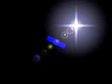
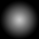
| 好了,我们现在开始吧。我将使用4个对立的纹理来制造我们的镜头光晕,第一和二个光晕图像被放置在光源处,第三和第四个图像将根据视点的位置和方向动态的生成。纹理的图像如下所示:
现在你在头脑里应该有了一个大慨地图像了吧。我们来说说何时我们应该绘制光晕,一般来说平时我们是看不见这些光晕的,只有当我们对准光源的时候才能看见这些。所以我们首先要获得视景体的数据,下面的函数可以帮我们完成这个功能。 |
// 获得当前视景体的6个平面方程的参数
void glCamera::UpdateFrustum()
{
    GLfloat   clip[16];
	GLfloat   proj[16];
    GLfloat   modl[16];
    GLfloat   t;
//返回投影矩阵
glGetFloatv( GL_PROJECTION_MATRIX, proj );
//返回模型变换矩阵
glGetFloatv( GL_MODELVIEW_MATRIX, modl );
//计算剪切矩阵,即上面两个矩阵的乘积
clip[ 0] = modl[ 0] * proj[ 0] + modl[ 1] * proj[ 4] + modl[ 2] * proj[ 8] +
modl[ 3] * proj[12];
clip[ 1] = modl[ 0] * proj[ 1] + modl[ 1] * proj[ 5] + modl[ 2] * proj[ 9] +
modl[ 3] * proj[13];
clip[ 2] = modl[ 0] * proj[ 2] + modl[ 1] * proj[ 6] + modl[ 2] * proj[10] +
modl[ 3] * proj[14];
clip[ 3] = modl[ 0] * proj[ 3] + modl[ 1] * proj[ 7] + modl[ 2] * proj[11] +
modl[ 3] * proj[15];
clip[ 4] = modl[ 4] * proj[ 0] + modl[ 5] * proj[ 4] + modl[ 6] * proj[ 8]
+ modl[ 7] * proj[12];
clip[ 5] = modl[ 4] * proj[ 1] + modl[ 5] * proj[ 5] + modl[ 6] * proj[ 9] +
modl[ 7] * proj[13];
clip[ 6] = modl[ 4] * proj[ 2] + modl[ 5] * proj[ 6] + modl[ 6] * proj[10] +
modl[ 7] * proj[14];
clip[ 7] = modl[ 4] * proj[ 3] + modl[ 5] * proj[ 7] + modl[ 6] * proj[11] +
modl[ 7] * proj[15];
clip[ 8] = modl[ 8] * proj[ 0] + modl[ 9] * proj[ 4] + modl[10] * proj[ 8]
+ modl[11] * proj[12];
clip[ 9] = modl[ 8] * proj[ 1] + modl[ 9] * proj[ 5] + modl[10] * proj[ 9] +
modl[11] * proj[13];
clip[10] = modl[ 8] * proj[ 2] + modl[ 9] * proj[ 6] + modl[10] * proj[10] +
modl[11] * proj[14];
clip[11] = modl[ 8] * proj[ 3] + modl[ 9] * proj[ 7] + modl[10] * proj[11] +
modl[11] * proj[15];
clip[12] = modl[12] * proj[ 0] + modl[13] * proj[ 4] + modl[14] * proj[ 8]
+ modl[15] * proj[12];
clip[13] = modl[12] * proj[ 1] + modl[13] * proj[ 5] + modl[14] * proj[ 9] +
modl[15] * proj[13];
clip[14] = modl[12] * proj[ 2] + modl[13] * proj[ 6] + modl[14] * proj[10] +
modl[15] * proj[14];
clip[15] = modl[12] * proj[ 3] + modl[13] * proj[ 7] + modl[14] * proj[11] +
modl[15] * proj[15];
//提取右面的平面方程系数
m_Frustum[0][0] = clip[ 3] - clip[ 0];
m_Frustum[0][1] = clip[ 7] - clip[ 4];
m_Frustum[0][2] = clip[11] - clip[ 8];
m_Frustum[0][3] = clip[15] - clip[12];
t = GLfloat(sqrt( m_Frustum[0][0] * m_Frustum[0][0] + m_Frustum[0][1] * m_Frustum[0][1]
+ m_Frustum[0][2] * m_Frustum[0][2] ));
m_Frustum[0][0] /= t;
m_Frustum[0][1] /= t;
m_Frustum[0][2] /= t;
m_Frustum[0][3] /= t;
//提取左面的平面方程系数
m_Frustum[1][0] = clip[ 3] + clip[ 0];
m_Frustum[1][1] = clip[ 7] + clip[ 4];
m_Frustum[1][2] = clip[11] + clip[ 8];
m_Frustum[1][3] = clip[15] + clip[12];
t = GLfloat(sqrt( m_Frustum[1][0] * m_Frustum[1][0] + m_Frustum[1][1] * m_Frustum[1][1]
+ m_Frustum[1][2] * m_Frustum[1][2] ));
m_Frustum[1][0] /= t;
m_Frustum[1][1] /= t;
m_Frustum[1][2] /= t;
m_Frustum[1][3] /= t;
//提取下面的平面方程系数
m_Frustum[2][0] = clip[ 3] + clip[ 1];
m_Frustum[2][1] = clip[ 7] + clip[ 5];
m_Frustum[2][2] = clip[11] + clip[ 9];
m_Frustum[2][3] = clip[15] + clip[13];
t = GLfloat(sqrt( m_Frustum[2][0] * m_Frustum[2][0] + m_Frustum[2][1] * m_Frustum[2][1]
+ m_Frustum[2][2] * m_Frustum[2][2] ));
m_Frustum[2][0] /= t;
m_Frustum[2][1] /= t;
m_Frustum[2][2] /= t;
m_Frustum[2][3] /= t;
//提取上面的平面方程系数
m_Frustum[3][0] = clip[ 3] - clip[ 1];
m_Frustum[3][1] = clip[ 7] - clip[ 5];
m_Frustum[3][2] = clip[11] - clip[ 9];
m_Frustum[3][3] = clip[15] - clip[13];
t = GLfloat(sqrt( m_Frustum[3][0] * m_Frustum[3][0] + m_Frustum[3][1] * m_Frustum[3][1]
+ m_Frustum[3][2] * m_Frustum[3][2] ));
m_Frustum[3][0] /= t;
m_Frustum[3][1] /= t;
m_Frustum[3][2] /= t;
m_Frustum[3][3] /= t;
//提取远面的平面方程系数
m_Frustum[4][0] = clip[ 3] - clip[ 2];
m_Frustum[4][1] = clip[ 7] - clip[ 6];
m_Frustum[4][2] = clip[11] - clip[10];
m_Frustum[4][3] = clip[15] - clip[14];
t = GLfloat(sqrt( m_Frustum[4][0] * m_Frustum[4][0] + m_Frustum[4][1] * m_Frustum[4][1]
+ m_Frustum[4][2] * m_Frustum[4][2] ));
m_Frustum[4][0] /= t;
m_Frustum[4][1] /= t;
m_Frustum[4][2] /= t;
m_Frustum[4][3] /= t;
//提取近面的平面方程系数
m_Frustum[5][0] = clip[ 3] + clip[ 2];
m_Frustum[5][1] = clip[ 7] + clip[ 6];
m_Frustum[5][2] = clip[11] + clip[10];
m_Frustum[5][3] = clip[15] + clip[14];
t = GLfloat(sqrt( m_Frustum[5][0] * m_Frustum[5][0] + m_Frustum[5][1] * m_Frustum[5][1]
+ m_Frustum[5][2] * m_Frustum[5][2] ));
m_Frustum[5][0] /= t;
m_Frustum[5][1] /= t;
m_Frustum[5][2] /= t;
m_Frustum[5][3] /= t;
}
| 现在我们可以测试一个点或圆是否在视景体内了。下面的函数可以测试一个点是否在视景体内。 |
BOOL glCamera::PointInFrustum(glPoint p)
{
	int i;

	for(i = 0; i < 6; i++)
	{
		if(m_Frustum[i][0] * p.x + m_Frustum[i][1] * p.y + m_Frustum[i][2] * p.z + m_Frustum[i][3] <= 0)
		{
			return(FALSE);
		}
	}
	return(TRUE);
}
下面的函数用来测试某个点是否位于当前场景物体的前面: |
bool glCamera::IsOccluded(glPoint p)
{
	GLint viewport[4];
	GLdouble mvmatrix[16], projmatrix[16];
	GLdouble winx, winy, winz;
	GLdouble flareZ;
	GLfloat bufferZ;
glGetIntegerv (GL_VIEWPORT, viewport);
glGetDoublev (GL_MODELVIEW_MATRIX, mvmatrix);
glGetDoublev (GL_PROJECTION_MATRIX, projmatrix);
// 返回顶点p在单位立方体中的位置
gluProject(p.x, p.y, p.z, mvmatrix, projmatrix, viewport, &winx, &winy,
&winz);
flareZ = winz;
// 读取点(winx,winy)的深度坐标
glReadPixels(winx, winy,1,1,GL_DEPTH_COMPONENT, GL_FLOAT, &bufferZ);
// 如果深度坐标小于点的坐标,则返回true
if (bufferZ < flareZ)
return true;
//否则返回false
else
return false;
}
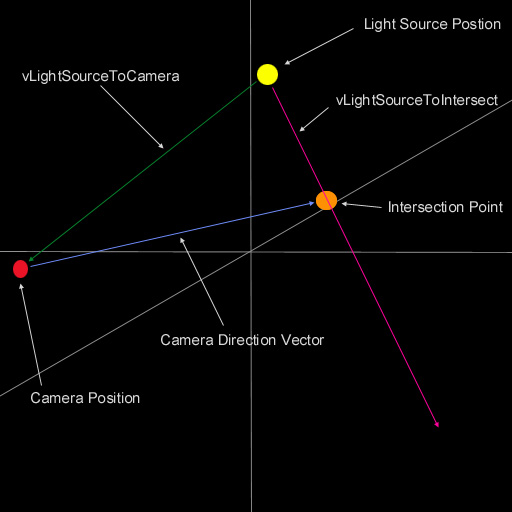
| 我们通过检测光源是否正对我们的视线来决定是否绘制光晕,但如果你的视点超过了光源的位置,则会发生看不见光晕的现象。为了避免这种现象,我们在移动视点的使用,也相应的移动我们的光源。为了在视点和光源之间绘制多个光晕,我们需要计算之间的向量,下面的代码完成这个功能: |
//下面的函数完成具体的渲染光晕的任务
void glCamera::RenderLensFlare()
{
	GLfloat Length = 0.0f;
// 如果我们的光源在我们的视线范围内,则绘制它
if(SphereInFrustum(m_LightSourcePos, 1.0f) == TRUE)
{
vLightSourceToCamera = m_Position - m_LightSourcePos; //
计算光源到我们视线的距离
Length = vLightSourceToCamera.Magnitude();
//下面三个函数计算光源位置到光晕结束位置之间的向量
ptIntersect = m_DirectionVector * Length;
ptIntersect += m_Position;
vLightSourceToIntersect = ptIntersect - m_LightSourcePos;
Length = vLightSourceToIntersect.Magnitude();
vLightSourceToIntersect.Normalize();
glEnable(GL_BLEND);
glBlendFunc(GL_SRC_ALPHA, GL_ONE);
glDisable(GL_DEPTH_TEST);
glEnable(GL_TEXTURE_2D);
|
首先我们需要找到光源位置和视点位置之间的向量,接下来我们需要在视线的方向设置一个插值点,这个点的距离必须和光源位置和视点位置之间的距离相等。完成以后,我们找出可以产生光晕的方向,即下图红线的方向,在这个线上我们可以绘制我们的光晕。
|
		if (!IsOccluded(m_LightSourcePos))	//如果光晕可见
		{
			// 渲染中间的光晕
			RenderBigGlow(0.60f, 0.60f, 0.8f, 1.0f, m_LightSourcePos, 16.0f);
			RenderStreaks(0.60f, 0.60f, 0.8f, 1.0f, m_LightSourcePos, 16.0f);
			RenderGlow(0.8f, 0.8f, 1.0f, 0.5f, m_LightSourcePos, 3.5f);
//绘制到光晕结束位置的0.1处的光晕
pt = vLightSourceToIntersect * (Length * 0.1f);
pt += m_LightSourcePos;
RenderGlow(0.9f, 0.6f, 0.4f, 0.5f, pt, 0.6f);
//绘制到光晕结束位置的0.15处的光晕
pt = vLightSourceToIntersect * (Length * 0.15f);
pt += m_LightSourcePos;
RenderHalo(0.8f, 0.5f, 0.6f, 0.5f, pt, 1.7f);
//绘制到光晕结束位置的0.175处的光晕
pt = vLightSourceToIntersect * (Length * 0.175f);
pt += m_LightSourcePos;
RenderHalo(0.9f, 0.2f, 0.1f, 0.5f, pt, 0.83f);
//绘制到光晕结束位置的0.285处的光晕
pt = vLightSourceToIntersect * (Length * 0.285f);
pt += m_LightSourcePos;
RenderHalo(0.7f, 0.7f, 0.4f, 0.5f, pt, 1.6f);
//绘制到光晕结束位置的0.2755处的光晕
pt = vLightSourceToIntersect * (Length * 0.2755f);
pt += m_LightSourcePos;
RenderGlow(0.9f, 0.9f, 0.2f, 0.5f, pt, 0.8f);
//绘制到光晕结束位置的0.4755处的光晕
pt = vLightSourceToIntersect * (Length * 0.4775f);
pt += m_LightSourcePos;
RenderGlow(0.93f, 0.82f, 0.73f, 0.5f, pt, 1.0f);
//绘制到光晕结束位置的0.49处的光晕
pt = vLightSourceToIntersect * (Length * 0.49f);
pt += m_LightSourcePos;
RenderHalo(0.7f, 0.6f, 0.5f, 0.5f, pt, 1.4f);
//绘制到光晕结束位置的0.65处的光晕
pt = vLightSourceToIntersect * (Length * 0.65f);
pt += m_LightSourcePos;
RenderGlow(0.7f, 0.8f, 0.3f, 0.5f, pt, 1.8f);
//绘制到光晕结束位置的0.63处的光晕
pt = vLightSourceToIntersect * (Length * 0.63f);
pt += m_LightSourcePos;
RenderGlow(0.4f, 0.3f, 0.2f, 0.5f, pt, 1.4f);
//绘制到光晕结束位置的0.8处的光晕
pt = vLightSourceToIntersect * (Length * 0.8f);
pt += m_LightSourcePos;
RenderHalo(0.7f, 0.5f, 0.5f, 0.5f, pt, 1.4f);
//绘制到光晕结束位置的0.7825处的光晕
pt = vLightSourceToIntersect * (Length * 0.7825f);
pt += m_LightSourcePos;
RenderGlow(0.8f, 0.5f, 0.1f, 0.5f, pt, 0.6f);
//绘制到光晕结束位置的1.0处的光晕
pt = vLightSourceToIntersect * (Length * 1.0f);
pt += m_LightSourcePos;
RenderHalo(0.5f, 0.5f, 0.7f, 0.5f, pt, 1.7f);
//绘制到光晕结束位置的0.975处的光晕
pt = vLightSourceToIntersect * (Length * 0.975f);
pt += m_LightSourcePos;
RenderGlow(0.4f, 0.1f, 0.9f, 0.5f, pt, 2.0f);
}
glDisable(GL_BLEND );
glEnable(GL_DEPTH_TEST);
glDisable(GL_TEXTURE_2D);
}
}
| 好了,下面的函数用来绘制四种不同的光晕 |
//绘制Halo形的光晕
void glCamera::RenderHalo(GLfloat r, GLfloat g, GLfloat b, GLfloat a, glPoint p, GLfloat scale)
{
	glPoint q[4];

	q[0].x = (p.x - scale);
	q[0].y = (p.y - scale);

	q[1].x = (p.x - scale);
	q[1].y = (p.y + scale);

	q[2].x = (p.x + scale);
	q[2].y = (p.y - scale);

	q[3].x = (p.x + scale);
	q[3].y = (p.y + scale);

	glPushMatrix();
	glTranslatef(p.x, p.y, p.z);
	glRotatef(-m_HeadingDegrees, 0.0f, 1.0f, 0.0f);
	glRotatef(-m_PitchDegrees, 1.0f, 0.0f, 0.0f);
	glBindTexture(GL_TEXTURE_2D, m_HaloTexture);
	glColor4f(r, g, b, a);

	glBegin(GL_TRIANGLE_STRIP);
		glTexCoord2f(0.0f, 0.0f);
		glVertex2f(q[0].x, q[0].y);
		glTexCoord2f(0.0f, 1.0f);
		glVertex2f(q[1].x, q[1].y);
		glTexCoord2f(1.0f, 0.0f);
		glVertex2f(q[2].x, q[2].y);
		glTexCoord2f(1.0f, 1.0f);
		glVertex2f(q[3].x, q[3].y);
	glEnd();
	glPopMatrix();
}
//绘制Gloew形的光晕
void glCamera::RenderGlow(GLfloat r, GLfloat g, GLfloat b, GLfloat a, glPoint
p, GLfloat scale)
{
glPoint q[4];
q[0].x = (p.x - scale);
q[0].y = (p.y - scale);
q[1].x = (p.x - scale);
q[1].y = (p.y + scale);
q[2].x = (p.x + scale);
q[2].y = (p.y - scale);
q[3].x = (p.x + scale);
q[3].y = (p.y + scale);
glPushMatrix();
glTranslatef(p.x, p.y, p.z);
glRotatef(-m_HeadingDegrees, 0.0f, 1.0f, 0.0f);
glRotatef(-m_PitchDegrees, 1.0f, 0.0f, 0.0f);
glBindTexture(GL_TEXTURE_2D, m_GlowTexture);
glColor4f(r, g, b, a);
glBegin(GL_TRIANGLE_STRIP);
glTexCoord2f(0.0f, 0.0f);
glVertex2f(q[0].x, q[0].y);
glTexCoord2f(0.0f, 1.0f);
glVertex2f(q[1].x, q[1].y);
glTexCoord2f(1.0f, 0.0f);
glVertex2f(q[2].x, q[2].y);
glTexCoord2f(1.0f, 1.0f);
glVertex2f(q[3].x, q[3].y);
glEnd();
glPopMatrix();
}
//绘制BigGlow形的光晕
void glCamera::RenderBigGlow(GLfloat r, GLfloat g, GLfloat b, GLfloat a, glPoint
p, GLfloat scale)
{
glPoint q[4];
q[0].x = (p.x - scale);
q[0].y = (p.y - scale);
q[1].x = (p.x - scale);
q[1].y = (p.y + scale);
q[2].x = (p.x + scale);
q[2].y = (p.y - scale);
q[3].x = (p.x + scale);
q[3].y = (p.y + scale);
glPushMatrix();
glTranslatef(p.x, p.y, p.z);
glRotatef(-m_HeadingDegrees, 0.0f, 1.0f, 0.0f);
glRotatef(-m_PitchDegrees, 1.0f, 0.0f, 0.0f);
glBindTexture(GL_TEXTURE_2D, m_BigGlowTexture);
glColor4f(r, g, b, a);
glBegin(GL_TRIANGLE_STRIP);
glTexCoord2f(0.0f, 0.0f);
glVertex2f(q[0].x, q[0].y);
glTexCoord2f(0.0f, 1.0f);
glVertex2f(q[1].x, q[1].y);
glTexCoord2f(1.0f, 0.0f);
glVertex2f(q[2].x, q[2].y);
glTexCoord2f(1.0f, 1.0f);
glVertex2f(q[3].x, q[3].y);
glEnd();
glPopMatrix();
}
//绘制Streaks形的光晕
void glCamera::RenderStreaks(GLfloat r, GLfloat g, GLfloat b, GLfloat a, glPoint
p, GLfloat scale)
{
glPoint q[4];
q[0].x = (p.x - scale);
q[0].y = (p.y - scale);
q[1].x = (p.x - scale);
q[1].y = (p.y + scale);
q[2].x = (p.x + scale);
q[2].y = (p.y - scale);
q[3].x = (p.x + scale);
q[3].y = (p.y + scale);
glPushMatrix();
glTranslatef(p.x, p.y, p.z);
glRotatef(-m_HeadingDegrees, 0.0f, 1.0f, 0.0f);
glRotatef(-m_PitchDegrees, 1.0f, 0.0f, 0.0f);
glBindTexture(GL_TEXTURE_2D, m_StreakTexture);
glColor4f(r, g, b, a);
glBegin(GL_TRIANGLE_STRIP);
glTexCoord2f(0.0f, 0.0f);
glVertex2f(q[0].x, q[0].y);
glTexCoord2f(0.0f, 1.0f);
glVertex2f(q[1].x, q[1].y);
glTexCoord2f(1.0f, 0.0f);
glVertex2f(q[2].x, q[2].y);
glTexCoord2f(1.0f, 1.0f);
glVertex2f(q[3].x, q[3].y);
glEnd();
glPopMatrix();
}
你可以使用w,s,a,d变换摄像机的方向,1,2显示/关闭各种信息参数。C给摄像机一个固定的速度,X停止它。 上面就是这个教程的全部了,所有的问题,评论和抱怨都欢迎。当然我不是第一个作这个效果的人,下面是其他方面相关的文章:
|