Owning Palette: Simulation VIs and Functions
Installed With: Control Design and Simulation Module
Executes the simulation diagram until the Simulation Loop reaches the simulation final time or until the Halt Simulation function stops the execution programmatically. You must place all Simulation functions within a Simulation Loop or in a simulation subsystem. You also can place simulation subsystems within a Simulation Loop or another simulation subsystem, or you can place simulation subsystems on a block diagram outside a Simulation Loop or run the simulation subsystems as stand-alone VIs.

 Place on the block diagram Place on the block diagram |  Find on the Functions palette Find on the Functions palette |
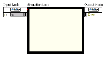
The Simulation Loop has an Input Node and an Output Node. Use the Input Node to configure simulation parameters programmatically. You also can configure these parameters interactively using the Configure Simulation Parameters dialog box. Access this dialog box by double-clicking the Input Node or by right-clicking the border and selecting Configure Simulation Parameters from the shortcut menu.
 | Note Parameters that you programmatically configure using the Input Node override any settings that you make in the Configure Simulation Parameters dialog box. |
The Simulation Loop has an Error input on the Input Node and an Error output on the Output Node. These error terminals send error information through the simulation diagram. If the Error input detects an error, the simulation diagram returns the error information in the Error output and does not execute the simulation. If an error occurs while the Simulation Loop is executing, the simulation stops running and returns the error information in the Error output.