Owning Palette: Optimal Design VIs
Installed With: Control Design and Simulation Module
Calculates parameter values that optimize a specified cost function while keeping parameters and outputs within specified bounds. This VI uses a finite-horizon time-domain simulation to obtain these values.
 | Note This VI uses the Constrained Nonlinear Optimization VI, which uses the sequential quadratic programming (SQP) algorithm to compute optimal parameter values. |

 Place on the block diagram Place on the block diagram |  Find on the Functions palette Find on the Functions palette |
 | Inequality Constraints specifies the upper and lower envelopes within which the following variables must lie: control actions, outputs, rate of change of control actions, and rate of change of outputs. Refer to the Details section for information about these envelopes. | ||||||||||||||||||||||||||||||||||||||||||||||||||
 | User Defined Objective Function Path specifies the path to a custom objective function. If you define a custom objective function, you also must specify the Bounds corresponding to User Defined Objective Function Path parameter.
You can use the SIM Objective Function template, located in the labview\templates\Simulation\Optimal Design directory, to design a custom objective function.
| ||||||||||||||||||||||||||||||||||||||||||||||||||
 | Parameter Bounds specifies the minimum and maximum values of each parameter, forming the region in which this VI searches for optimal values. The nth element of this parameter corresponds to the nth element of the Initial Parameters parameter. | ||||||||||||||||||||||||||||||||||||||||||||||||||
 | Initial Parameters specifies the parameters you want to optimize and the initial values of each parameter. This VI uses these initial values to search the parameter space for optimal values. You define the parameter space using the Parameter Bounds parameter. The structure of the Initial Parameters parameter depends on the value you specify for the System response type parameter.
Refer to the Details section for information about the structure of this parameter.
| ||||||||||||||||||||||||||||||||||||||||||||||||||
 | System Data specifies information about the system on which this VI operates. You can use the SIM Construct Default System VI to obtain this information. | ||||||||||||||||||||||||||||||||||||||||||||||||||
 | Solver Parameters specifies the parameters, such as the ordinary differential equation (ODE) solver, this VI uses to simulate the finite-horizon time-domain response of the dynamic system model. These parameters are identical to the ones you configure using the Configure Simulation Parameters dialog box. | ||||||||||||||||||||||||||||||||||||||||||||||||||
 | Problem Specification specifies the type of system response, inequality constraints, and cost function. You can select from a pre-defined list or substitute custom types.
| ||||||||||||||||||||||||||||||||||||||||||||||||||
 | Initial Parameters Mesh specifies the method this VI uses to generate additional sets of initial parameter values. Generating more than one set of initial parameter values increases the possibility of finding global optimal parameter values instead of local optimal parameter values. This parameter also specifies the number of initial parameter value sets to generate.
| ||||||||||||||||||||||||||||||||||||||||||||||||||
 | error in describes error conditions that occur before this VI or function runs.
The default is no error. If an error occurred before this VI or function runs, the VI or function passes the error in value to error out. This VI or function runs normally only if no error occurred before this VI or function runs. If an error occurs while this VI or function runs, it runs normally and sets its own error status in error out. Use the Simple Error Handler or General Error Handler VIs to display the description of the error code.
Use exception control to treat what is normally an error as no error or to treat a warning as an error.
Use error in and error out to check errors and to specify execution order by wiring error out from one node to error in of the next node.
| ||||||||||||||||||||||||||||||||||||||||||||||||||
 | stopping criteria is the collection of conditions that terminate the optimization. If (function tolerance AND parameter tolerance AND gradient tolerance) OR max iterations OR max function calls then optimization terminates.
| ||||||||||||||||||||||||||||||||||||||||||||||||||
 | Bounds corresponding to User Defined Objective Function specifies the minimum and maximum inequality constraint values for the User Defined Objective Function. | ||||||||||||||||||||||||||||||||||||||||||||||||||
 | beginning state contains the initial values of the inequality constraint function, the lagrangian multipliers, and the hessian. beginning state is typically the ending state of a previous optimization and allows a warm start of the optimization.
| ||||||||||||||||||||||||||||||||||||||||||||||||||
 | cno settings contains additional tolerance and termination settings that are specific to this algorithm.
| ||||||||||||||||||||||||||||||||||||||||||||||||||
 | Signals returns the time response for all outputs and control actions corresponding to each element of the Optimal costs parameter.
| ||||||||||||||||||||||||||||||||||||||||||||||||||
 | Design Parameters returns the set of parameter values that minimize the specified cost function. These values are the optimal parameter values. | ||||||||||||||||||||||||||||||||||||||||||||||||||
 | Design Cost returns the result of the specified cost function if you apply the values from the Design parameters parameter. | ||||||||||||||||||||||||||||||||||||||||||||||||||
 | Optimal parameters returns a list of possible optimal parameter values. Each column of this array corresponds to one parameter you specified in the Parameter Bounds parameter. Each row of this array corresponds to one search for optimal values. | ||||||||||||||||||||||||||||||||||||||||||||||||||
 | Optimal costs returns the results of the specified cost function that correspond to each row of the Optimal parameters array. | ||||||||||||||||||||||||||||||||||||||||||||||||||
 | error out contains error information. If error in indicates that an error occurred before this VI or function ran, error out contains the same error information. Otherwise, it describes the error status that this VI or function produces.
Right-click the error out front panel indicator and select Explain Error from the shortcut menu for more information about the error.
|
SIM Optimal Design Details
Defining Inequality Constraint Envelopes
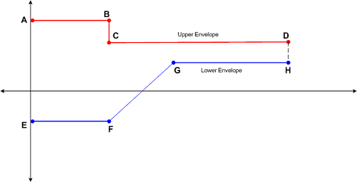
An envelope is a piecewise linear curve defined by the end points of linear segments. The following figure shows a typical pair of envelopes.

where points A,B,C, and D define the upper envelope and points E, F, G, and H define the lower envelope.
The Inequality Constraints parameter contains four arrays. Each array specifies the constraints on either the control actions, outputs, rate of change of control actions, or rate of change of outputs. Each array also includes two clusters, Upper Envelope Points and Lower Envelope Points. Both of these clusters include two arrays, Time and Amplitude. These arrays specify the x and y coordinates, respectively, that define the points that make up the envelope.
 | Note Instead of specifying individual points, you can use the Graphically Specify Inequality Constraints VI, located in the labview\examples\Control and Simulation\Simulation\Optimal Control Design\Graphically Specify Inequality Constraints directory, to draw the upper and lower envelopes. |
Cost Function Types
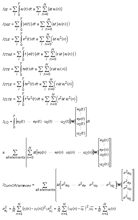
The following equations define the types of cost function J you can specify for the Cost type parameter.

| where | e(t) is the error, defined as r(t) – y(t) |
| t is the simulation time | |
| r is the reference signal | |
| y is the output | |
| u is the control action | |
| n is the current time response sample | |
| N is the maximum number of samples in the time response | |
| W is the weight matrix you define using the Weights for cost function parameter | |
| i is the index of the current output channel |
Specifying the System Response Type and Defining Initial Parameter Values
The structure of the Initial Parameters parameter depends on the value you select for the System response type parameter.
If you select Default SISO - Optimize C, this VI returns optimal gain values KP, KI, and KD for a parallel PID controller defined by the following equation:

where a = 0.01.
In this situation, the first element of the Initial Parameters parameter must be the initial value of KP. The second and third elements must be the initial values of KI and KD, respectively.
If you select Default SISO - Optimize F1 or Default SISO - Optimize F2, this VI returns optimal coefficient values for the following transfer function equation that defines these filters.

In this situation, the Initial Parameters parameter contains the initial values of the numerator and denominator coefficients. You must separate this parameter into an equal number of numerator and denominator coefficients. Therefore, if a coefficient is 0, you must enter 0 in the appropriate element instead of leaving that element blank.
For example, if Initial Parameters is [5 6 0 0 0 6 3 0 9 2], this VI interprets the numerator coefficients as [5 6 0 0 0] in ascending powers of s. This VI interprets the denominator coefficients as [6 3 0 9 2] in ascending powers of s. Therefore, the following transfer function equation initially defines filter.

Examples
Refer to the following VIs for examples of using the SIM Optimal Design VI:
- PID Design for Second Order Continuous System VI: labview\examples\Control and Simulation\Simulation\Optimal Control Design
- PID Design for Second Order Discrete System VI: labview\examples\Control and Simulation\Simulation\Optimal Control Design


