SIM Construct Default System VI

Simulation VI and Function

SIM Construct Default System VI

Owning Palette: Optimal Design VIs

Installed With: Control Design and Simulation Module

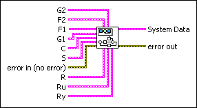
Constructs a dynamic system model you can wire to the System Data input of the SIM Optimal Design VI. This dynamic system model consists of a controller, a plant, a sensor, and three filters.

Details  Examples

 Place on the block diagram  Find on the Functions palette
G2 specifies information about the output feedforward filter.
F2 specifies information about the control feedforward filter.
F1 specifies information about the reference filter.
G1 specifies information about the plant.
C specifies information about the controller.
S specifies information about the sensor.
error in describes error conditions that occur before this VI or function runs. The default is no error. If an error occurred before this VI or function runs, the VI or function passes the error in value to error out. This VI or function runs normally only if no error occurred before this VI or function runs. If an error occurs while this VI or function runs, it runs normally and sets its own error status in error out. Use the Simple Error Handler or General Error Handler VIs to display the description of the error code. Use exception control to treat what is normally an error as no error or to treat a warning as an error. Use error in and error out to check errors and to specify execution order by wiring error out from one node to error in of the next node.
status is TRUE (X) if an error occurred before this VI or function ran or FALSE (checkmark) to indicate a warning or that no error occurred before this VI or function ran. The default is FALSE.
code is the error or warning code. The default is 0. If status is TRUE, code is a nonzero error code. If status is FALSE, code is 0 or a warning code.
source specifies the origin of the error or warning and is, in most cases, the name of the VI or function that produced the error or warning. The default is an empty string.
R specifies information about the reference input signal to the controller C. Refer to the Details section for the information about how this signal applies to the dynamic system model.
Signal Type specifies the type of reference signal.

0None—Specifies a reference signal of 0.
1Step (default)—Specifies a step input signal. You can control the height of the step signal using the Step/impulse scaling factor parameter.
2Impulse—Specifies an input impulse signal. You can control the height of the impulse signal using the Step/impulse scaling factor parameter.
3User defined—Specifies a custom signal.
Step/impulse scaling factor specifies the factor by which this VI scales the input signal. This parameter is valid only if you specify Step or Impulse for the Signal Type parameter.
User Defined Input specifies a custom input signal. This parameter is valid only if you select User defined for the Signal Type parameter. The values you enter in this parameter must be uniformly-spaced. The time step between values is determined by the Time Step of the fixed step-size ordinary differential equation (ODE) solver you specify in the Solver Parameters parameter of the SIM Optimal Design VI. If you specify a variable step-size ODE solver, this VI resamples the custom input values based on the current Time Step of the ODE solver.
Ru specifies information about the input signal to the plant G1. This input signal passes through the control feedforward filter F2. Refer to the Details section for the information about how this signal applies to the dynamic system model.
Signal Type specifies the type of reference signal.

0None—Specifies a reference signal of 0.
1Step (default)—Specifies a step input signal. You can control the height of the step signal using the Step/impulse scaling factor parameter.
2Impulse—Specifies an input impulse signal. You can control the height of the impulse signal using the Step/impulse scaling factor parameter.
3User defined—Specifies a custom signal.
Step/impulse scaling factor specifies the factor by which this VI scales the input signal. This parameter is valid only if you specify Step or Impulse for the Signal Type parameter.
User Defined Input specifies a custom input signal. This parameter is valid only if you select User defined for the Signal Type parameter. The values you enter in this parameter must be uniformly-spaced. The time step between values is determined by the Time Step of the fixed step-size ordinary differential equation (ODE) solver you specify in the Solver Parameters parameter of the SIM Optimal Design VI. If you specify a variable step-size ODE solver, this VI resamples the custom input values based on the current Time Step of the ODE solver.
Ry specifies information about the input signal that this VI combines with output from the plant G1. This input signal passes through the output feedforward filter G2. Refer to the Details section for the information about how this signal applies to the dynamic system model.
Signal Type specifies the type of reference signal.

0None—Specifies a reference signal of 0.
1Step (default)—Specifies a step input signal. You can control the height of the step signal using the Step/impulse scaling factor parameter.
2Impulse—Specifies an input impulse signal. You can control the height of the impulse signal using the Step/impulse scaling factor parameter.
3User defined—Specifies a custom signal.
Step/impulse scaling factor specifies the factor by which this VI scales the input signal. This parameter is valid only if you specify Step or Impulse for the Signal Type parameter.
User Defined Input specifies a custom input signal. This parameter is valid only if you select User defined for the Signal Type parameter. The values you enter in this parameter must be uniformly-spaced. The time step between values is determined by the Time Step of the fixed step-size ordinary differential equation (ODE) solver you specify in the Solver Parameters parameter of the SIM Optimal Design VI. If you specify a variable step-size ODE solver, this VI resamples the custom input values based on the current Time Step of the ODE solver.
System Data returns information about the dynamic system that this VI constructs. You can wire this output to the System Data input of the SIM Optimal Design VI. Refer to the Details section for the structure of this dynamic system.
error out contains error information. If error in indicates that an error occurred before this VI or function ran, error out contains the same error information. Otherwise, it describes the error status that this VI or function produces. Right-click the error out front panel indicator and select Explain Error from the shortcut menu for more information about the error.
status is TRUE (X) if an error occurred or FALSE (checkmark) to indicate a warning or that no error occurred.
code is the error or warning code. If status is TRUE, code is a nonzero error code. If status is FALSE, code is 0 or a warning code.
source describes the origin of the error or warning and is, in most cases, the name of the VI or function that produced the error or warning.

SIM Construct Default System Details

Dynamic System Structure

This VI constructs a dynamic system model with the following structure:

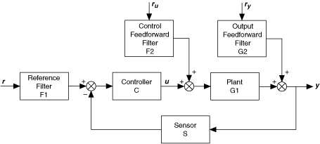
Dynamic System Components

G2, F2, F1, G1, C, and S consist of one or more transfer functions and information about the transfer function(s), such as delays.

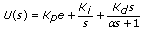
By default, C is a parallel proportional integral derivative (PID) controller defined by the following equation:

Defining a Custom Reference Signal

The System Data parameter of this VI contains the Signal Parameters Array parameter, which specifies values for reference signals ru, ry, and r. If you define a custom dynamic system, ru and ry must be the first two elements of the Signal Parameters Array, respectively. You can define custom reference signals starting with the third element.

Examples

Refer to the following VIs for examples of using the SIM Construct Default System VI:

  • PID Design for Second Order Continuous System VI: labview\examples\Control and Simulation\Simulation\Optimal Control Design

     Open example  Browse related examples

  • PID Design for Second Order Discrete System VI: labview\examples\Control and Simulation\Simulation\Optimal Control Design

     Open example  Browse related examples