Rate Limiter Function
Owning Palette: Nonlinear Systems Functions
Installed With: Control Design and Simulation Module
Limits the rate of change of a signal.
| Dialog Box Options |
| Block Diagram Inputs |
| Block Diagram Outputs |
 Place on the block diagram Place on the block diagram |
Find on the Functions palette |
Dialog Box Options
| Parameter | Description |
|---|---|
| Polymorphic instance | Specifies whether this function is Scalar or Vector. The default value is Scalar. |
| Parameters | Lists all the parameters associated with this function. Select a parameter from this list to configure the parameter. When you select a parameter, the parameter and its associated Parameter source control appear in the Parameter Information section of the configuration dialog box. |
| Preview | Displays a graphical preview, if available, of the function output or configuration. |
| Parameter Information | Contains the parameters you can configure for this function. You must select a parameter from the Parameters list to make that parameter and its associated Parameter source control visible in the Parameter Information section of the configuration dialog box. |
| Parameter source | Specifies whether you configure this parameter using the Configuration Dialog Box or a Terminal on the simulation diagram. The default value is Configuration Dialog Box. If you select Terminal, LabVIEW displays an input for that parameter on the simulation diagram, and you can wire values to that input to configure this function programmatically. If you select Configuration Dialog Box, LabVIEW removes that input from the simulation diagram. You then must set the value for this parameter inside the configuration dialog box. |
| negative slew rate | Specifies the lower limit of the rate of change of the signal. The default value is –1. |
| positive slew rate | Specifies the upper limit of the rate of change of the signal. The default value is 1. |
Block Diagram Inputs
| Parameter | Description |
|---|---|
| negative slew rate | Specifies the lower limit of the rate of change of the signal. The default value is –1. |
| positive slew rate | Specifies the upper limit of the rate of change of the signal. The default value is 1. |
| input | Specifies the signal to which you want to apply the function. |
Block Diagram Outputs
| Parameter | Description |
|---|---|
| output | Returns the signal that results from applying the function to the input signal. |
Rate Limiter Details
The following equations define the output of this function.
Given 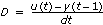
then
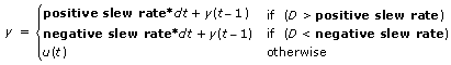
| where | u is the input |
| y is the output | |
| t is the current simulation time | |
| D is the rate of change of the signal |
Feedthrough Behavior
All input/output pairs of this function have direct feedthrough behavior.
Example
Refer to the SimEx rate limiter VI in the labview\examples\Control and Simulation\Simulation\Nonlinear directory for an example of using the Rate Limiter VI.
Open example Browse related examples