Noise Figure Measurement
All devices have inherent noise. When noise is quantified, it is usually referred to the device input. In other words, all noise power a UUT inherits is assumed to come from its input. The noise figure of a UUT is the ratio in dB of its noise power to the noise power that a matched resistive load would deliver at room temperature. If you terminate a UUT input with a matched resistive load (typically 50 Ω) and measure the noise power density at its output (No), the noise figure (NF) is given by the following equation:

where G is the power gain of the UUT, k ≈ 1.38 ×10⁻²³ is Boltzmanns constant, and T0 ≈ 290° K is the room temperature.
If you use the RF Signal Analyzer to measure the output noise of a UUT, the result of the measurement contains not only UUT noise but also noise intrinsic to the RF Signal Analyzer. If the UUT gain (G) is known, compute the noise figure of the UUT with the following equation:

where Nrfsa is the noise measured by the RF Signal Analyzer when its input is terminated with a matched resistive load and Nm is the measured noise with UUT attached. Both Nrfsa and Nm are given in Watts; G is a linear power gain.
Measurement Setup
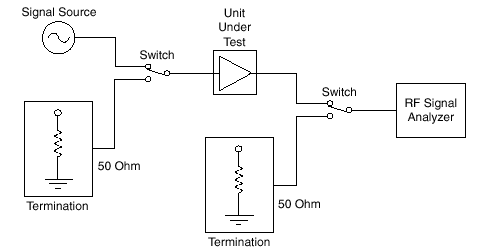
A typical noise figure measurement setup is shown in the following figure.

Typical Noise Figure Measurement Setup
Measuring Noise Figure with the RF Signal Analyzer
To measure the noise figure, complete the following steps:
- Turn on the RF Signal Analyzer and let it warm up for 20 minutes.
- Turn on the UUT if it is active.
- Set the RF Signal Analyzer to the frequency of interest, and decrease the resolution bandwidth to about 1 kHz.
- Terminate the RF Signal Analyzer input with a broadband resistive load.
- Obtain an average reading of the noise level. Make sure to take enough readings to obtain a good average.
- Convert a reading taken in dBm to watts and normalize it to 1 Hz by dividing by the resolution bandwidth. This value is the noise floor of the RF Signal Analyzer at that frequency, which is Nrfsa in this document.
- Remove the load termination from the RF Signal Analyzer input.
- Attach the output of the UUT to the RF Signal Analyzer input.
- Input a known small signal into the UUT input. This signal level should be less then 10 dB below the 1 dB compression point of the UUT.
- Measure the output signal level on the RF Signal Analyzer to determine the gain (G) of the UUT.
- Remove the signal source and terminate the UUT input with a broadband resistive load.
- Make another averaged reading of the noise with the UUT attached by repeating steps 5 and 6. This average is the noise value for the UUT and the RF Signal Analyzer (Nm).
- Substitute your values into the equation:
as follows to determine the UUT noise figure:
- The value from step 6 is Nrfsa
- The value from step 10 is G
- The value from step 12 is Nm