1 dB Gain Compression Measurement
An amplifier maintains a constant gain for low-level input signals. However, at higher input levels, the amplifier goes into saturation and its gain decreases. The 1 dB compression point (P1dB) indicates the power level that causes the gain to drop by 1 dB from its small signal value.
Measurement Setup
Measuring the 1 dB gain compression point of a device requires driving the UUT into compression without driving the RF Signal Analyzer into compression. This requires proper attenuation at the RF Signal Analyzer and a signal source of sufficient power to compress the UUT. You can apply attenuation by programming the internal input attenuators or by using external attenuation.
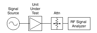
The 1 dB compression point is derived from the gain relationship between output power and input power. Using the measurement setup shown in the figure below, source amplitude is slowly increased while the UUT output is monitored.

Typical 1 dB Gain Compression Setup
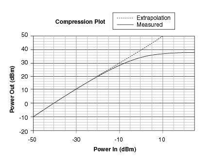
Output power is plotted against input power as shown in the following figure.

Gain Compression Plot
The straight line on this graph is an extrapolation of the small signal gain of the UUT. The input 1 dB compression point is the input power that causes the UUT gain to drop by 1 dB from this small signal value, or approximately 12 dBm in this case.
Understanding RF Signal Analyzer Compression Limits
Like all signal analysis devices, the RF Signal Analyzer is not completely linear and will eventually reach compression. However, the RF Signal Analyzer architecture possesses a high degree of linearity, and its compression point is typically 5 dBm or higher.
Ensure accurate UUT compression measurements by limiting the signal at the RF Signal Analyzer input mixer to 20 dB below the compression point listed in the NI PXI-5660 RF Vector Signal Analyzer Specifications document included in your RF Signal Analyzer kit.
Choosing the Optimal RF Signal Analyzer Attenuation Setting
Choosing the optimal attenuation settings for a UUT compression measurement requires you take the following factors into account:
- The maximum output signal of your UUT must be attenuated to 1020 dB less than the compression point of the RF Signal Analyzer.
- The resolution bandwidth setting of the RF Signal Analyzer must be low enough that small signals used to determine the linear gain of the UUT are not overwhelmed with noise from the RF Signal Analyzer.
To set the proper RF Signal Analyzer attenuation level for a compression test on a UUT with known output compression estimate and known approximate gain, complete the following steps:
- Set the RF Signal Analyzer mixer level to 20 dBm and its reference level to 10 dB above the estimated UUT compression point.
mixer level = reference level – attenuation.
- Set the RF Signal Analyzer center frequency to your intended testing frequency, its span to 1 MHz, and its resolution bandwidth to 1 kHz.
- Inject a signal into the UUT small enough that its output level is at least 20 dB below the estimated UUT compression point. If the UUT output signal level is too close to the noise floor of the RF Signal Analyzer, decrease the RF Signal Analyzer resolution bandwidth.
- Increase the input signal to the UUT. If the output signal has reached 5 dB below the RF Signal Analyzer reference level and compression of the UUT has not been reached, increase the reference level by 10 dB.
- Repeat step 4 until compression appears in the UUT.
The setting you obtain is the optimal attenuation setting.