Owning Palette: Advanced FIR Filter Design VIs
Installed With: Digital Filter Design Toolkit
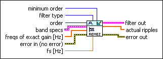
Creates an equi-ripple filter using the Remez exchange method.

 Place on the block diagram Place on the block diagram |  Find on the Functions palette Find on the Functions palette |
 | minimum order specifies whether this VI uses the filter order you specify or calculates the minimum filter order. The default is user defined.
If you select minEven or minOdd, this VI ignores the order input and determines the minimum required filter order. You also must provide a ripple constraint for each band in the ripple constraint input of band specs.
| ||||||||||||
 | filter type specifies the type of filter that this VI creates.
| ||||||||||||
 | order specifies the filter order. The value of order must be greater than zero. The default is 20. order +1 equals the number of coefficients or filter taps. Increasing the value can narrow the transition band. | ||||||||||||
 | band specs specifies the target frequency response that the filter frequency response fits. Each element of the array represents one frequency band specification. You can enter one or more points in ascending order to describe the frequency response in each band. This VI connects the points to form the continuous ideal frequency response for the band. The frequency range between two consecutive bands is a transition band.
The frequency response you describe with the band specs input is the signed amplitude response. You can provide negative target amplitude values. However, if the filter type input is Minimum Phase or Maximum Phase, the frequency response you describe with the band specs input is the magnitude response, and all target amplitude values must be positive.
| ||||||||||||
 | freqs of exact gain specifies frequency points where the amplitude must have exactly the same value as the amplitude input in band specs. If a frequency point does not appear in band specs, this VI interpolates the amplitude linearly. | ||||||||||||
 | error in describes error conditions that occur before this VI or function runs.
The default is no error. If an error occurred before this VI or function runs, the VI or function passes the error in value to error out. This VI or function runs normally only if no error occurred before this VI or function runs. If an error occurs while this VI or function runs, it runs normally and sets its own error status in error out. Use the Simple Error Handler or General Error Handler VIs to display the description of the error code. Use error in and error out to check errors and to specify execution order by wiring error out from one node to error in of the next node.
| ||||||||||||
 | fs specifies the sampling frequency in hertz. The value must be greater than zero. The default is 1, which is the normalized sampling frequency. | ||||||||||||
 | filter out returns a new filter. | ||||||||||||
 | actual ripples returns the actual ripple magnitude in each band specified in band specs. | ||||||||||||
 | error out contains error information. If error in indicates that an error occurred before this VI or function ran, error out contains the same error information. Otherwise, it describes the error status that this VI or function produces.
Right-click the error out front panel indicator and select Explain Error from the shortcut menu for more information about the error.
|
DFD Remez Design Details
In the Remez exchange method, the filter frequency response best fits the target response in the Chebyshev sense. The Remez Design VI employs either complex approximation or magnitude approximation to create the design.
The design criterion for complex approximation is defined by the following equation:

The design criterion for magnitude approximation is defined by the following equation:

where D(wi) is the ideal frequency response, H(wi) is the frequency response of the designed filter, and W(i) is the positive weight at the ith frequency point. Symmetric, Antisymmetric, Differentiator, and Hilbert filter types use complex approximation. Minimum Phase and Maximum Phase filter types use magnitude approximation.
Examples
Refer to the following VIs for examples of using the DFD Remez Design VI:
- EquiRipple Filter Design - DFD VI: labview\examples\Digital Filter Design\AALXMPL
- Advanced Remez FIR Filter Design VI: labview\examples\Digital Filter Design\Floating-Point Filters\Conventional
- Arbitrary Shape Lowpass Filter Design VI: labview\examples\Digital Filter Design\Floating-Point Filters\Conventional
 on amplitude response. This option uses a built-in weighting function that is inversely proportional to frequency to achieve a constant percentage error ripple versus the amplitude of the frequency response.


