Owning Palette: Advanced IIR Filter Design VIs
Installed With: Digital Filter Design Toolkit
Designs an infinite impulse response (IIR) or finite impulse response (FIR) filter with a frequency response that matches the response you request in terms of the least pth norm algorithm. You can use either the iterative reweighted least square (IRLS) method or the Newton method that this VI provides to design a filter. You must manually select the polymorphic instance you want to use.
Use the pull-down menu to select an instance of this VI.
 Place on the block diagram Place on the block diagram | Find on the Functions palette |
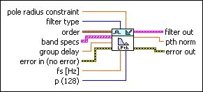
DFD Least Pth Norm Design by IRLS

 | pole radius constraint specifies the maximum pole radius for the new filter. The default is 0.99. A small pole radius decreases the possibility of filter instability resulting from finite precision effects. However, a small pole radius can affect the potential sharpness of the magnitude response adversely. The range of valid values for pole radius constraint is (0, 1]. If you specify an invalid value, this VI ignores this input and applies no constraint to the pole radius. | ||||||||||||
 | filter type specifies the type of filter that this VI creates.
| ||||||||||||
 | order specifies the filter numerator and denominator order.
For FIR filters, order+1 equals the number of coefficients. For IIR filters, the numerator order+1 equals the number of forward coefficients and the denominator order+1 equals the number of reverse coefficients.
| ||||||||||||
 | band specs specifies the target frequency response that the filter frequency response fits. Each element in the array represents one frequency band specification. You can enter one or more points in ascending order to describe the frequency response in each band. This VI connects the points to form the continuous ideal frequency response for the band. The frequency range between two consecutive bands is a transition band.
| ||||||||||||
| group delay specifies the group delay for all bands. The default is 5. You can specify any real number. For a specific frequency, this VI adjusts the phase response using the phase input in the band specs in combination with group delay. | ||||||||||||
 | error in describes error conditions that occur before this VI or function runs.
The default is no error. If an error occurred before this VI or function runs, the VI or function passes the error in value to error out. This VI or function runs normally only if no error occurred before this VI or function runs. If an error occurs while this VI or function runs, it runs normally and sets its own error status in error out. Use the Simple Error Handler or General Error Handler VIs to display the description of the error code. Use error in and error out to check errors and to specify execution order by wiring error out from one node to error in of the next node.
| ||||||||||||
| fs specifies the sampling frequency in hertz. The value must be greater than zero. The default is 1, which is the normalized sampling frequency. | ||||||||||||
 | p specifies the order of norm. The value of p must be between 2 and 128. When p equals 2, this VI returns the least squares solution. As you increase the value of p, the solution asymptotically approaches an equi-ripple magnitude solution. When p equals 128, this VI returns a nearly equi-ripple magnitude response. The default is 128. This input corresponds to the p parameter in the equations in the Details section of this topic. | ||||||||||||
 | filter out returns a new filter. | ||||||||||||
 | pth norm returns the pth norm for the design. | ||||||||||||
 | error out contains error information. If error in indicates that an error occurred before this VI or function ran, error out contains the same error information. Otherwise, it describes the error status that this VI or function produces.
Right-click the error out front panel indicator and select Explain Error from the shortcut menu for more information about the error.
|
 on amplitude response.


DFD Least Pth Norm Design by Newton
| pole radius constraint specifies the maximum pole radius for the new filter. The default is 0.99. A small pole radius decreases the possibility of filter instability resulting from finite precision effects. However, a small pole radius can affect the potential sharpness of the magnitude response adversely. The range of valid values for pole radius constraint is (0, 1]. If you specify an invalid value, this VI ignores this input and applies no constraint to the pole radius. | ||||||||||||
| filter type specifies the type of filter that this VI creates.
| ||||||||||||
| order specifies the filter numerator and denominator order.
For FIR filters, order+1 equals the number of coefficients. For IIR filters, the numerator order+1 equals the number of forward coefficients and the denominator order+1 equals the number of reverse coefficients.
| ||||||||||||
| band specs specifies the target frequency response that the filter frequency response fits. Each element in the array represents one frequency band specification. You can enter one or more points in ascending order to describe the frequency response in each band. This VI connects the points to form the continuous ideal frequency response for the band. The frequency range between two consecutive bands is a transition band.
| ||||||||||||
| group delay specifies the group delay for all bands. The default is 5. You can specify any real number. For a specific frequency, this VI adjusts the phase response using the phase input in the band specs in combination with group delay. | ||||||||||||
| error in describes error conditions that occur before this VI or function runs.
The default is no error. If an error occurred before this VI or function runs, the VI or function passes the error in value to error out. This VI or function runs normally only if no error occurred before this VI or function runs. If an error occurs while this VI or function runs, it runs normally and sets its own error status in error out. Use the Simple Error Handler or General Error Handler VIs to display the description of the error code. Use error in and error out to check errors and to specify execution order by wiring error out from one node to error in of the next node.
| ||||||||||||
| fs specifies the sampling frequency in hertz. The value must be greater than zero. The default is 1, which is the normalized sampling frequency. | ||||||||||||
| p specifies the order of norm. The value of p must be between 2 and 128. When p equals 2, this VI returns the least squares solution. As you increase the value of p, the solution asymptotically approaches an equi-ripple magnitude solution. When p equals 128, this VI returns a nearly equi-ripple magnitude response. The default is 128. This input corresponds to the p parameter in the equations in the Details section of this topic. | ||||||||||||
| filter out returns a new filter. | ||||||||||||
| pth norm returns the pth norm for the design. | ||||||||||||
| error out contains error information. If error in indicates that an error occurred before this VI or function ran, error out contains the same error information. Otherwise, it describes the error status that this VI or function produces.
Right-click the error out front panel indicator and select Explain Error from the shortcut menu for more information about the error.
|
DFD Least Pth Norm Design Details
You can design either an IIR or FIR filter using this VI. The following equation shows the frequency response of an IIR filter with N zeroes and M poles:
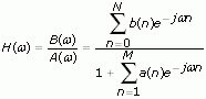
| where | B(ω) is the Fourier transform of the forward coefficients |
| A(ω) is the Fourier transform of the reverse coefficients | |
| b(n) is the set of forward coefficients | |
| a(n) is the set of reverse coefficients |
When M equals zero, the IIR filter reduces to an FIR filter. Usually, a(0) is normalized to one, as shown in the equation above.
Given a complex-valued ideal frequency response D(ω), the DFD Least Pth Norm Design VI designs optimal IIR filters using the least pth norm algorithm. The VI uses either complex approximation or magnitude approximation to create the design. The following equation is the complex approximation:
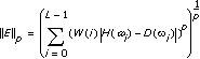
| where | W(i) is a positive weight at the ith frequency point |
| H is the response of the designed filter | |
| D is the target response | |
| L is the number of frequency points used to perform the calculation | |
| p is the pth norm |
The following equation is the magnitude approximation:
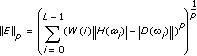
The equations are minimized in terms of filter coefficients a(n) and b(n).
If you set the filter type input to Minimum Phase or Maximum Phase, the DFD Least Pth Norm Design VI performs magnitude approximation and ignores the phase information of D(ω). If you set the filter type input to Symmetric, Antisymmetric, Differentiator, or Hilbert, the DFD Least Pth Norm Design VI uses complex approximation.
The phase response of the filter θoverall(ω) is specified by phase in the band specs θspecified(ω) and group delay τgp, as shown in the following equation:
θoverall(ω) = –τgpω + θspecified(ω)
Examples
Refer to the following VIs for examples of using the DFD Least Pth Norm Design VI:
- Arbitrary Shape Lowpass Filter Design VI: labview\examples\Digital Filter Design\Floating-Point Filters\Conventional Open example Browse related examples
- Lpth Norm Complex Approximation-Compensate Channel Distortion VI: labview\examples\Digital Filter Design\Floating-Point Filters\Conventional Open example Browse related examples
- LPth Norm IIR Filter Design VI: labview\examples\Digital Filter Design\Floating-Point Filters\Conventional Open example Browse related examples
- LPth Norm Weighting Filter Design VI: labview\examples\Digital Filter Design\Floating-Point Filters\Conventional Open example Browse related examples