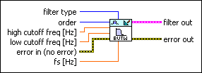
DFD Butterworth Design VI
Owning Palette: Advanced IIR Filter Design VIs
Installed With: Digital Filter Design Toolkit
Creates a digital Butterworth infinite impulse response (IIR) filter.
You can use the DFD Butterworth Order Estimation VI to estimate order.

 Place on the block diagram Place on the block diagram |  Find on the Functions palette Find on the Functions palette |
 | filter type specifies the type of filter that this VI creates.
| ||||||||
 | order specifies the digital filter order. The value of order must be greater than zero. The default is 2. If you set filter type to Lowpass or Highpass, the digital filter order you specify must equal the analog prototype filter order. If you set filter type to Bandstop or Bandpass, the digital filter order you specify must be an even number that equals two times the analog prototype filter order. Increasing the value can narrow the transition band. | ||||||||
 | high cutoff freq specifies the high cutoff frequency in hertz. The value must be greater than low cutoff freq. The default is 0.45. This VI uses this input only for bandpass and bandstop filter design. The cutoff frequency that you specify corresponds to the half-power frequency or the 3 dB frequency. | ||||||||
 | low cutoff freq specifies the low cutoff frequency in hertz. The default is 0.12. The cutoff frequency that you specify corresponds to the half-power frequency or the 3 dB frequency. | ||||||||
 | error in describes error conditions that occur before this VI or function runs.
The default is no error. If an error occurred before this VI or function runs, the VI or function passes the error in value to error out. This VI or function runs normally only if no error occurred before this VI or function runs. If an error occurs while this VI or function runs, it runs normally and sets its own error status in error out. Use the Simple Error Handler or General Error Handler VIs to display the description of the error code. Use error in and error out to check errors and to specify execution order by wiring error out from one node to error in of the next node.
| ||||||||
 | fs specifies the sampling frequency in hertz. The value must be greater than zero. The default is 1, which is the normalized sampling frequency. | ||||||||
 | filter out returns a new filter. | ||||||||
 | error out contains error information. If error in indicates that an error occurred before this VI or function ran, error out contains the same error information. Otherwise, it describes the error status that this VI or function produces.
Right-click the error out front panel indicator and select Explain Error from the shortcut menu for more information about the error.
|
DFD Butterworth Design Details
Butterworth filters have the following characteristics:
- Smooth frequency response at all frequencies and monotonically decreasing or increasing magnitude response in the transition band.
- Maximally flat at frequencies of zero and one-half the sampling frequency.
Butterworth filters do not always provide an acceptable accurate approximation of the ideal frequency response because the filter has slow roll off in the transition band. Use Chebyshev, Inverse Chebyshev, or Elliptic filters to achieve a sharper roll off.
Examples
Refer to the following VIs for examples of using the DFD Butterworth Design VI:


