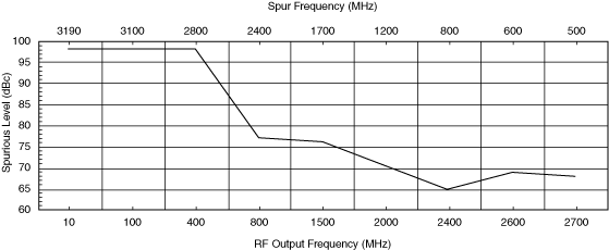
Spurs
Several different categories define the spurious behavior of the NI 5610 upconverter module. The first category includes spurs that are independent of the input signal and occurring at frequencies less than 2.7 GHz. All spurs fitting this criteria are less than or equal to –80 dBm in amplitude.
Spurs due to intermodulation distortion (IMD) are dependent on the drive and change as the drive level changes. The following equation predicts how the IMD products will change with output power:
IMDTOI = 2(OIP3 – Pout)
IMDSOI = OIP2 – Pout
Third-order intermodulation distortion (IMDTOI) is the difference in dB or dBc between Pout and the distortion signals.
 |
Note IMDTOI degrades by 2 dB for every 1 dB increase in Pout for the third order distortion terms, and degrades by 1 dB for every 1 dB increase in Pout for the second order terms. |
The second category of spurs are dependent on the input signal and occur at frequencies less than 2.7 GHz, but not within ±10 MHz of the desired output signal. All spurs in this category are less than –80 dBc in amplitude, with the exception of one spur at approximately –60 dBc. The output frequency for this spur can be determined using the following equation:
fspur = 3225 – fout – fin
where
fspur, fout, and fin are in MHz.

The third category of spurs includes those within ±10 MHz of the carrier frequency. These spurs are the result of signals modulating one of the local oscillator (LO) signals. These spurs are below –50 dBc for frequencies less than 1 kHz and below –60 dBc for frequencies from 1 to 2 kHz. Beyond 2 kHz, spurious levels are below –70 dBc.
The final category of spurs are greater than 2.7 GHz. An LO spur occurs at 2.88 GHz and at multiples of 2.88 GHz; these spurs are less than –80 dBm in amplitude. As part of the architecture of the NI 5610 upconverter module, a broad tuning LO tunes over the range of 3.2 to 5.9 GHz. The frequency of this LO is always approximately 3.2 GHz greater than the output signal.
When the LOCAL OSC OUT 0 connector on the NI 5610 front panel is disabled by using the Local Oscillator Out 0 Enabled property or NIRFSG_ATTR_LOCAL_OSCILLATOR_OUT_0_ENABLED attribute, the LO leakage at the RF OUT connector is typically less than –80 dBm for output frequencies greater than 100 MHz. For output frequencies <100 MHz, the LO leakage at the RF OUT connector is dependent on the filters in the output section and can be as great as –35 dBm.
 |
Note At frequencies greater than 100 MHz, the LO level is affected by the attenuators in the RF signal chain. |
When the LOCAL OSC OUT 0 connector on the NI 5610 upconverter module front panel is enabled, LO leakage is about –45 dBm for output frequencies greater than 100 MHz. For frequencies less than 100 MHz, LO leakage is dependent on the filters in the output section and on the output power setting. However, even with the NI 5670 output power set to the minimum level, the LO leakage at the RF OUT front panel connector (with the LOCAL OSC OUT O connector enabled) could be as great as –40 dBm.
This section does not address harmonic-related spurs.