Phase Continuity
 |
Note This section always applies to the NI 5670. This section only applies to the NI 5671 when the DUC is disabled. |
An array containing a sine wave is phase-continuous if the phase of its last point is equal to the phase of its first point, minus the phase difference between any two adjacent samples. In other words, a sinusoidal waveform array is phase-continuous if it contains an integer number of cycles of the sinusoid.
An arbitrary array is phase-continuous if the phase of its last point is equal to the phase of its first point, minus the phase difference between any two adjacent samples for every frequency component of the array.
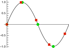
The user-specified baseband IQ waveform written to the AWG module must be phase-continuous, or a phase glitch appears in the RF output signal when the generation loops back to the beginning of the waveform in AWG onboard memory. NI-RFSG upconverts the user-provided baseband IQ signal to IF by multiplying it with a carrier. The IF waveform array is phase-continuous only if the array contains an integer number of cycles of the IF carrier frequency. The following figure represents a sine wave sampled at two different sample rates. Circles represent phase-continuous sampling of the sine wave. Squares represent non-phase-continuous sampling of the sine wave.

Phase glitches in the RF output signal that are due to phase discontinuities in the IF waveform can be addressed by repeating the original IF waveform. For example, you can double an array containing 1.5 cycles of the IF waveform to form a new phase-continuous IF waveform array containing 3 cycles.
For some combinations of waveform size and IF frequency, you may need to repeat the original waveform multiple times to attain phase continuity. In fact, if the original array contains an irrational number of cycles, it is impossible to arrive at an exact integer number of cycles in the repeated array. However, you can get close and then coerce the IF frequency to the nearest quantum to get an exact integer number of cycles. NI-RFSG software coerces the IF waveform by as much as the specified frequency tolerance to minimize array size. This ensures phase continuity at the expense of introducing a frequency quantization error1. The maximum possible frequency error introduced is inversely proportional to the size of the IF waveform array; therefore, it is possible to make the frequency quantization error arbitrarily small as long as the array size can be arbitrarily large.
In practice, you can ensure phase continuity and keep the frequency error of the IF carrier within a given tolerance (determined by your memory size). A large memory size allows a small frequency tolerance, while a small memory size can give rise to a larger frequency tolerance error.
 |
Note You may continue to encounter "out of memory" errors (or "memory full" errors) when the original waveform is smaller than the specified maximum waveform size. To overcome this problem, increase the frequency tolerance setting. This change allows NI-RFSG to coerce to an RF frequency that requires fewer buffer repetitions. |
By default, NI-RFSG assumes that the user-specified input IQ array is phase-continuous. NI-RFSG repeats the input IQ array as necessary to ensure phase continuity in the IF waveform after IQ-to-IF upconversion.
If phase continuity is irrelevant to your application (for example, your array represents a burst signal with a significant portion of the envelope equal to zero power), disable array repetition by using the Phase Continuity Enabled property or the NIRFSG_ATTR_PHASE_CONTINUITY_ENABLED attribute. This step can often save processing time and AWG onboard memory, but it does not ensure phase coherence in the IF waveform between bursts.
 |
Note Disabling phase continuity does not force the output waveform to be non phase-continuous; rather, it stops NI-RFSG from repeating the waveform to ensure phase continuity. |
1 The term frequency error refers to the difference between the user-requested RF output frequency and the actual RF output frequency of the NI RF signal generator. The NI-RFSG driver coerces the output frequency as close to the requested value as allowed by the Frequency Tolerance (Hz) property or the NIRFSG_ATTR_FREQUENCY_TOLERANCE attribute. The absolute frequency error in the output value of the NI RF signal generator is determined by the 10 MHz reference used during generation. When using the upconverter module onboard reference, this error is less than 50 ppb.