NI RF Vector Signal Generator Hardware Operation
The NI RF vector signal generator hardware consists of two parts: the NI 5421/5441/5442 arbitrary waveform generator (AWG) module and the NI 5610 RF upconverter module. The NI 5421/5441/5442 generates a signal centered at an intermediate frequency (IF) between 15 and 35 MHz. The IF signal is sent to the NI 5610, which frequency-translates it to center between 250 kHz and 2.7 GHz.
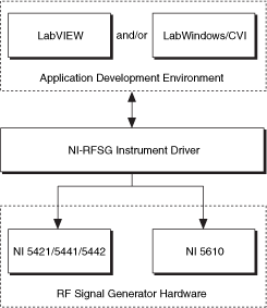
The NI-RFSG driver software operates both hardware modules as a single instrument by handling all module programming and interaction. When you specify a carrier frequency and power for the RF output signal, NI-RFSG selects the appropriate IF frequency and power level settings for the NI 5421/5441/5442 AWG module, and the frequency shift, gain, and attenuation settings for the NI 5610 upconverter module. The following figure illustrates the NI RF signal generator driver architecture.

The power and carrier frequency of the IF signal generated by the NI 5421/5441/5442 are determined by the NI-RFSG software. To optimize dynamic range, NI-RFSG attempts to use the full scale of the NI 5421/5441/5442 digital-to-analog converter (DAC) and adjusts output signal power by means of the NI 5610 attenuators.
The NI 5610 contains a stable and accurate 10 MHz frequency reference. A coaxial cable feeds the frequency reference from the NI 5610 10 MHz OUT (TO AWG CLK IN) front panel connectors to the NI 5421/5441/5442 CLK IN front panel connectors. The NI 5421/5441/5442 locks its internal reference clock to this reference.
 |
Note NI RF signal generator operation requires that the NI 5610 module front panel connector labeled 10 MHz OUT (TO AWG CLK IN) be connected to the NI 5421/5441/5442 module front panel connector labeled CLK IN. Most timing configurations generate an error if this interconnection is not in place. |
The NI 5610 reference can also be locked to an external 10 MHz frequency reference. The source of this external reference can be either the REF IN connector on the NI 5610 module front panel or the PXI_CLK10 backplane signal.
The NI 5610 accomplishes frequency shifting by mixing the IF signal with local oscillators in the NI 5610 signal chain circuit. One of these local oscillator (LO) signals can be tuned from 3.2 GHz to 5.9 GHz. A separate output connector on the NI 5610 module front panel, LOCAL OSC OUT 0, allows you to export this LO signal if you have enabled the oscillator output using the Local Oscillator Out 0 Enabled property or the NIRFSG_ATTR_LOCAL_OSCILLATOR_OUT_0_ENABLED attribute.