Phase-Locked Loop Bandwidth
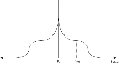
The phase-locked loop (PLL) bandwidth characterizes loop dynamics such as tuning speed, stability, and phase noise shaping. When the PLL bandwidth is designed for x Hz, it is measured at x Hz from the center of the carrier signal, as shown in the following figure. The region of frequency between the carrier and the PLL bandwidth is "inside the loop," and the region higher then the PLL bandwidth is "outside the loop."

Tuning speed increases with bandwidth and vice versa. PLL theory states that the phase noise of the local oscillator (LO) signal may be broken into the two following components:
- phase noise of the tuning oscillator
- noise from the loop components with the reference signal, inclusive
The tuning oscillator phase noise dominates the region outside the loop, while the region inside the loop is dominated by the loop components.
There are three possible loop bandwidth settings: LOW, MEDIUM, and HIGH. At the HIGH loop bandwidth setting, phase noise less than or equal to 10 kHz offset from the carrier is minimized. The HIGH setting is also used for instantaneous bandwidths less than 10 MHz. At lower settings (MEDIUM or LOW), the phase noise close to the carrier increases while phase noise outside the loop bandwidth frequency decreases. When signal bandwidth is set greater than 10 MHz, the only available loop bandwidth option is LOW. Use the Signal Bandwidth (Hz) property or the NIRFSG_ATTR_SIGNAL_BANDWIDTH to change loop bandwidth settings.