Trigger Sub-System
The trigger sub-system configures the type of event that triggers the oscilloscope. The global trigger sub-system properties are:
The IviScope Trigger Type property specifies the event that triggers the oscilloscope.
The IviScope Trigger Holdoff property specifies the length of time after the oscilloscope detects a trigger during which the oscilloscope ignores additional triggers. The IviScope Trigger Holdoff property only affects instrument operation when the oscilloscope requires multiple acquisitions to build a complete waveform. The oscilloscope requires multiple waveform acquisitions when the instrument uses equivalent time sampling or the acquisition type is set to envelope or average. The IviScope Trigger Coupling property specifies how the oscilloscope couples the trigger source signal to the trigger sub-system.
The properties from the above list can be set individually or they can be set as a group with the IviScope Configure Trigger and IviScope Configure Trigger Coupling VIs.
The following properties configure the edge trigger. These properties can be set individually or as a group with the IviScope Configure Edge Trigger Source VI.

Edge Triggers
The IviScope Trigger Source property specifies the source the oscilloscope monitors for the trigger event. The IviScope Trigger Level property specifies the voltage threshold for the trigger sub-system. Most of the trigger types use the value held in the IviScope Trigger Level property.
The IviScope Trigger Slope property specifies whether a positive or negative edge triggers the oscilloscope.
When the trigger type is edge, the values held in the IviScope Trigger Level and IviScope Trigger Slope properties define the trigger event. The oscilloscope triggers when the trigger source crosses the threshold level with the polarity the IviScope Trigger Level and IVISCOPE_ATTR_TRIGGER_SLOPE properties specify.
Triggering Overview
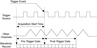
The following figure illustrates the relationship of the Trigger event and the acqStartTime parameter to the data the oscilloscope acquires in the waveform record. For this illustration, the trigger type is an edge trigger and the trigger source is a series of pulses. It is important to note that the trigger source can be an analog or digital signal and the trigger type can be any trigger type that this class driver defines.

Holdoff Overview
The following figure shows how the hold off effects the trigger sub-system. Ideally the trigger event occurs at condition '1', but sometimes the oscilloscope triggers on condition '2' because the signal crosses the trigger level. When you specify a hold off, the oscilloscope triggers on conditions '1' and '3', and ignores conditions '2' and '4'.

This IviScopeBase Capability group defines VIs that retrieve waveforms from the oscilloscope. These VIs return the following information:
- The waveform record as an array of voltage.
- The time that corresponds to the first point in the waveform array relative to the Trigger Even.
- The effective time interval between points in the waveform record