NetworkTrace
From Land Desktop Map 3D Samples
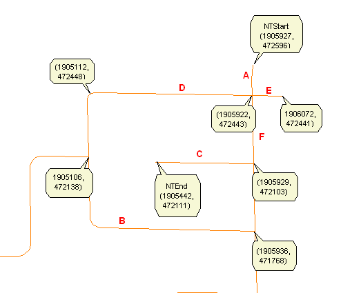
When you enter the NetworkTrace command on the Map command-line, you cause the NetworkTraceCommand method to be executed. This method uses an Autodesk.AutoCAD.EditorInput.Editor object to collect two command-line arguments from the user: the end point of a line in the map which represents the start point of the trace and the end point of a line, which represents the end point of the trace. It creates a NetworkTrace object and calls its RunNetworkTraceCommand method, passing in the start point and end point arguments. The graphic shows a portion of the map contained in the Roads.sdf file annotated to show the values of the start and end points selected using the Editor object as well as the points processed during the construction of the shortest path between the start and end points The letters in the graphic name the links for the purpose of the code walkthrough.
The RunNetworkTraceCommand method does the following:
- Checks the repository for the results of a previous run and if found, removes it.
- Creates an AcMapMap object and gets the current map.
- Gets the layers in the current map
- Looks for the layer whose name is “Roads”.
- Uses the “Roads” layer to create an MgResourceIdentifier object identifying the Roads.sdf file.
- Uses the “Roads” layer to get the schema name and class name belonging to the Roads.sdf file.
- Uses an MgFeatureService object, the “Roads” MgResourceIdentifier object, and the schema and class names to get the MgClassDefinition object.
- Uses the MgClassDefinition object to get the MgPropertyDefinitionCollection object containing the identity property definitions and from that the name of the identity property.
- Constructs
a SearchEngine object.
The constructor takes the following arguments:
- an MgFeatureService object
- an MgResourceIdentifier object identifying the feature source (Roads.sdf)
- the qualified feature class name
- the name of the feature’s default geometry property
- the name of the feature’s identity property
- the tolerance to be used to declare that two points intersect
- Searches for a path between the start and end points specified by the user. This is described in topic Search for a Path. The SearchPath method belongs to the SearchEngine object. If no path is found, an exception is thrown.
- Create a feature schema that will be applied to the Result.sdf file. It will have three properties: a geometry whose name is geometry, an identity property whose name is Id, and a data property whose name is OldId. This is described in topic CreateResultsFdoSchema.
- Creates an sdf file in the local filesystem that has the schema created in the previous step and the coordinate system of the current map. This file will contain the results of the network trace. This is described in topic CreateSdfFile.
- For
each feature ID in the shortest path list, does the following:
- Uses an MgFeatureService object, the MgResourceIdentifier object for the feature source, an MgFeatureQueryOptions object whose filter is set to “<idPropertyName> = <featureID>” to select the LineString from the feature source and put them in an MgFeatureReader object.
- Puts the feature properties into an MgPropertyCollection object. This is described in topic ReadFeature.
- Changes the name of the feature’s identity property to ‘OldId’ and the name of the geometry property to ‘geometry’ and add an identity property whose name is ‘Id’.
- Adds the feature to the Results.sdf using an MgInsertFeatures object, an MgFeatureCommandCollection object, and an MgFeatureService object.
- Adds the contents of the Result.sdf file to the map as a layer. This is described in AddAllToMap.
- Loops through the MgLayerCollection object until it finds the Result layer and changes the color of the layer. This is described in topic Highlight.
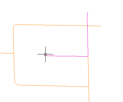
The graphic shows the result of adding the path to the map.