NI-RFSG Express VI (Arbitrary Waveform)

NI-RFSG LabVIEW

NI-RFSG Express VI (Arbitrary Waveform)

Configures and runs National Instruments RF signal generators using NI-RFSG to produce an arbitrary waveform signal.

You must place at least two NI-RFSG Express (Arbitrary Waveform) VIs on the block diagram for successful generation. Select Start generation for the generation mode in the first Express VI to start the continuous generation. Select Stop generation for the generation mode in the final Express VI to stop generation and close the NI-RFSG device handle. The following figure shows an example of how to wire the two instances of the Express VI to generate continuously until a stop button is pressed.
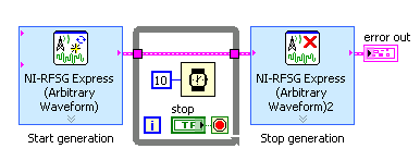
Dialog Box Options
Block Diagram Inputs
Block Diagram Outputs

Dialog Box Options

ParameterDescription
Configuration Contains the following options:
  • Device—Specifies the NI RF signal generator used. This ring control lists all NI RF signal generators installed on this computer that can be used by this Express VI. If you relaunch the VI and the selected RF signal generator is dimmed, it is no longer available.
  • Generation—Specifies the generation mode. Choose from the following options:
    • Start generation—Configures the NI RF signal generator to generate the waveform continuously and starts the generation. In this mode, the Express VI returns immediately after starting the generation. To stop the generation, drop another instance of this Express VI on the block diagram, select the same RF signal generator, and configure it to Stop generation.
    • Stop generation—Stops a continuous generation that was started by another instance of this Express VI that was configured to Start generation.
  • Frequency (Hz)—Specifies the center frequency of the generated RF signal.
  • Power level (dBm)—Specifies the average power level of the generated RF signal.
  • Bandwidth (Hz)—Specifies the signal bandwidth used by NI-RFSG for generating the RF output signal. The driver uses this value to optimally configure the center frequency of the upconverter to help minimize phase noise.
    The generated signal will not be filtered to achieve the set bandwidth. However, specifying a bandwidth smaller than the actual bandwidth of the signal could potentially result in spectral distortion.
    Note Note  The waveform preview graph tries to represent the ideal signal without any consideration for the Bandwidth control.
  • Data type—Specifies the data type of the input waveform.
  • Extract IQ rate from waveform—Specifies whether to use the waveform dt to determine the IQ rate.
  • IQ rate (S/s)—Specifies the IQ rate of the arbitrary waveform.
Trigger and Timing Contains the following options:
  • Trigger type—Specifies the type of trigger to use for starting waveform generation.
  • Trigger source—Specifies the trigger source terminal for the digital edge start trigger.
  • Edge—Specifies the active edge for the digital edge start trigger.
  • Reference clock source—Specifies the source of the reference clock signal. Only certain combinations of Reference clock source and PXI Chassis Clk10 source are valid.
  • PXI Chassis Clk 10 source—Specifies the signal driven to the 10 MHz reference clock on the PXI backplane. Only certain combinations of Reference clock source and PXI Chassis Clk10 source are valid.
  • Arb sample clock source—Specifies the sample clock source of the arbitrary waveform generator. To select Clk In, you must uncheck the Extract IQ rate from waveform option on the Configuration page.
  • Arb onboard sample clock mode—Specifies the clock mode on the arbitrary waveform generator.
  • External clock rate (Hz)—Displays the rate that the external clock must be set to. This value is calculated from the IQ rate set on the Configuration page.
Advanced Contains the following options:
  • Enable DUC pre-filter gain—Specifies whether to enable DUC pre-filter gain.
  • DUC pre-filter gain (dB)—Specifies the digital upconverter (DUC) pre-filter gain. Reduce this value to prevent overflow in the DUC interpolation filters. Other gains on the NI RF signal generator are automatically adjusted to compensate for non-unity DUC pre-filter gain.
  • Allow resampling—Specifies whether to allow resampling of the input waveform. Resampling only occurs if the selected device does not support the IQ rate of the input waveform. If the input waveform is phase continuous, the resampled waveform will also be phase continuous.
Graph viewSpecifies the information displayed in the waveform preview. Select from the following options:
  • I vs. Q
  • Power Spectrum

Block Diagram Inputs

ParameterDescription
IQ WaveformSpecifies the arbitrary waveform to generate.
error inDescribes error conditions that occur before this Express VI runs.

Block Diagram Outputs

ParameterDescription
error outContains error information. If error in indicates that an error occurred before this Express VI runs, error out contains the same error information. Otherwise, it describes the error status that this Express VI produces.