Filter

LabVIEW SignalExpress

Filter

Filters a time signal using an infinite impulse response (IIR) or finite impulse response (FIR) filter. Use this step to remove or attenuate unwanted frequencies from a signal using various standard filter types and topologies.

In LabVIEW SignalExpress, the Filter step filters the input signal continuously. The step resets the signal to its original value the first time the step runs, if LabVIEW SignalExpress detects a discontinuity in the input signal, or if you press the Reset Filter button.

In LabVIEW, the Filter Express VI filters the input signal continuously. The Express VI resets the signal to its original value the first time the Express VI runs, if LabVIEW detects a discontinuity in the input signal, or if the reset input receives a TRUE value.

Details  

ParameterDescription
Input SignalsDisplays the input signal to filter.
Autoscale amplitudeAutoscales the preview graph along the y-axis. The default is to autoscale the amplitude.
Displayed signalSpecifies the signal(s) to display in the preview graph(s). This option appears only when you select a group of signals for the input.
Note  If the input signals include scalar values that depend on the values of input waveform signals, you cannot specify to display all signals in the preview graph(s).
Output SignalsDisplays the filtered signal.
Autoscale amplitudeAutoscales the preview graph along the y-axis. The default is to autoscale the amplitude.
InputThe following option applies to the LabVIEW SignalExpress step:
  • Input signal—Specifies the input signal to filter.
ConfigurationContains the following option:
  • Filter Specifications—Contains the following options:
    • Mode—Specifies the mode of filter to use. You can select from the following options:
      • IIR filter—Specifies an IIR filter, which is a recursive digital filter with infinite impulse response. IIR filters operate on current and past input values and current and past output values. IIR filters can achieve the same level of attenuation as FIR filters but with fewer coefficients. For this reason, IIR filters can be faster and more efficient than FIR filters.
      • FIR filter—Specifies an FIR filter, which is a digital filter with finite impulse response. FIR filters operate only on current and past input values. Because an FIR filter does not depend on past outputs, the impulse response decays to zero in a finite amount of time. Use FIR filters for applications that require linear phase responses.
    • Type—Specifies the type of filter to use. You can select from the following options:
      • Lowpass—(Default) Passes low frequencies and attenuates high frequencies.
      • Highpass—Passes high frequencies and attenuates low frequencies.
      • Bandpass—Passes a certain band of frequencies. Use the Low cutoff (Hz) and the High cutoff (Hz) fields to specify the band.
      • Bandstop—Attenuates a certain band of frequencies. Use the Low cutoff (Hz) and the High cutoff (Hz) fields to specify the band.
    • Topology—[Mode: IIR Filter] Specifies the design type of an IIR filter. You can select from the following options:
      • Off—Does not filter the signal.
      • Butterworth—(Default) Applies a Butterworth filter to the signal. Butterworth filters have a smooth, monotonically decreasing frequency response.
      • Chebyshev—Applies a Chebyshev filter to the signal. Chebyshev filters can achieve a sharper transition between the passband and the stopband with a lower order filter than Butterworth filters.
      • Inverse Chebyshev—Applies an Inverse Chebyshev filter to the signal. Inverse Chebyshev filters are similar to Chebyshev filters, but they distribute the error over the stopband instead of the passband and are maximally flat in the passband instead of the stopband.
      • Elliptic—Applies an Elliptic filter to the signal. Elliptic filters minimize the peak error by distributing it over the passband and the stopband. Elliptic filters provide the sharpest transition between the passband and the stopband.
      • Bessel—Applies a Bessel filter to the signal. Bessel filters have maximally flat response in both magnitude and phase. You can use Bessel filters to reduce nonlinear phase distortion inherent in all IIR filters.
    • Order—[Mode: IIR filter] Determines the order of an IIR filter, which must be greater than zero. The default is 2. Increasing the value of Order causes the transition between the passband and the stopband to become steeper. However, as the value of Order increases, the processing speed becomes slower, and the number of distorted points at the start of the signal increases.
    • Number of taps—[Mode: FIR filter] Specifies the total number of FIR coefficients, which must be greater than zero. The default is 49. Increasing the value of taps causes the transition between the passband and the stopband to become steeper. However, as the value of Number of taps increases, the processing speed becomes slower.
    • Cutoff (Hz)—[Type: Lowpass, Highpass] Specifies the cutoff frequency of the filter when you select a Lowpass or Highpass filter type. The default is 100 Hz.
    • Low cutoff (Hz)—[Type: Bandpass, Bandstop] Specifies the lower cutoff frequency when you select a Bandpass or Bandstop filter type. The default is 100 Hz.
    • High cutoff (Hz)—[Type: Bandpass, Bandstop] Specifies the higher cutoff frequency when you select a Bandpass or Bandstop filter type. High cutoff (Hz) must be greater than Low cutoff (Hz) and observe the Nyquist criterion. The default is 200 Hz.
    • Filter Magnitude Response (dB)—Displays the magnitude response of the filter you specify.

Filter Details

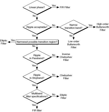
The best filter Mode, Type, and Topology to use depends on the analysis you want to perform. Use the following illustration as a guideline for selecting the appropriate filter for an analysis project: