Working with Materials and Textures
See Also: Class MtlBase, Class Mtl, Class Texmap, Class ShadeContext, Class StdMat, Class Mesh, Class INode.
Overview
This section provides information on working with materials and textures. This includes an overview of the principal classes, how plug-ins can access components of materials (such as their maps, colors, etc.), and how materials may be created and applied to nodes in the scene. Information is also provided about how the user interface is managed for plug-in materials and textures.
A texture and a material are similar in many ways. In MAX, every texture or material may have sub-texture or sub-materials. Materials that have sub-materials are referred to as meta-materials.
Overview of the Principal Classes
The following are the main classes associated with creating plug-in materials and textures.
This is the base class that the materials and texture classes are derived from.
This is the class plug-in materials are sub-classed from.
This is the class plug-in procedural textures are sub-classed from.
An instance of this class is passed into various methods associated with materials and texture maps. It provides data members and methods used in communication between the renderer and the plug-in material or texture.
A pointer to an instance of this class is a data member of the ShadeContext (RenderGlobalContext *globContext;). This can be used by materials, texmaps, etc. to retireve information about the global rendering enviornment. This is information such as the renderer in use, the project type for rendering, the output device width and height, several matrices for transforming between camera and world coordinates, the environment map, the atmospheric effects, the current time, field rendering information, and motion blur information.
This is an interface class passed to a material or texture map when it is being edited in the materials editor. The class has methods to do things such as add rollup pages to the dialog, remove rollup pages, and retrieve the current time (frame slider position).
Every MtlBase sub-class (i.e. texture map and material) defines a ParamDlg to manage its part of the material editor user interface. See the section below on Editing Material or Texture Parameters for details on how this class is used.
Most texture maps that use UVs will use a UVGen. This class encapsulates a lot of the user interface for setting mirroring, tiling and so on. The UVGen is given a MapSampler callback, and the plug-in lets the UVGen call it. This lets the UVGen figure out the components for anti-aliasing, and it includes any transform including scaling, rotation, moving, and noise on the UVs.
A texture map implements this class and passes it into the UVGen methods EvalUVMap(), EvalUVMapMono(), and EvalDeriv() to evaluate itself with tiling & mirroring. Each of the methods of this class are used to sample the map at a single UV coordinate.
This class generates Point3 coordinates based on the ShadeContext. A reference to one of these is referenced by all 3D texture maps. XYZGen does for 3D Texmaps what UVGen does for 2D Texmaps. It puts up the 3D "Coordinates" rollup, and supplies the 3D Texmap with transformed 3D coordinates.
This class may be used by textures to provide control over their output. The standard rollup page 'Output' is managed by this class. The Output Amount, RGB Level, and RGB Offset are settable. In the future this may be enhanced to include other things that are often desirable on the output stage such as tinting, color shifting, etc.
The following are the main classes associated with accessing properties of materials and textures:
This class provides access to the parameters of the 3ds max Standard material.
This class provides access to the developer alterable properties of the 3ds max Multi/Sub-Object material.
This class provides access to the parameters of the 3ds max Bitmap texture.
This class provides access to the parameters of the 3ds max UVGen class. These are the settings in the 'Coordinates' and 'Noise' rollups such as UV offsets, angle, blur, noise level, etc.
This class provides access to the parameter of the 3ds max XYZGen class.
This class provides access to the materials stored in a materials library. See the sample code below for an example of use.
Accessing Material Properties
This section covers how the various properties of a material may be retrieved from a node in the scene. These are properties such as color, mapping parameters, bitmaps used, etc.
In 3ds max there is only one material per node. In the INode class there are methods GetMtl() and SetMtl() that provide access to the node's material. GetMtl() returns a pointer to an instance of class Mtl.
virtual Mtl *GetMtl()=0;
Returns the renderer material for the node. If the value returned is NULL this means the user has not assigned a material to the node. In such a case the renderer simply uses the wireframe color of the node (as well as many defaults) for the rendering properties.
The material returned can be any material that may be assigned by the user. These include those from 3ds max itself as well as those created by third party developers. One may look at the Class_ID of the material to determine its type. For example, the 3ds max Standard material has a Class_ID of DMTL_CLASS_ID while the Multi/Sub-Object material uses MULTI_CLASS_ID. See List of Class_IDs to review the complete list provided by MAX.
Let's consider the case of accessing properties of the 3ds max Standard material first. If the Class_ID returned is DMTL_CLASS_ID then it's a Standard material. This material does not have any sub-materials, but has many parameters that a developer may need to access.
The primary class for accessing the Standard material is Class StdMat. It provides methods to get and set the material's properties. These are things like the shading limit, the diffuse, ambient and specular colors, and the shininess and opacity of the material. Developers may also need to access the mapping parameters, for example, to find the texture used in the diffuse slot. A developer may access these using MtlBase::GetSubTexmap(int i) and MtlBase::SetSubTexmap(int i, Texmap *m). The index passed to these method are a series of #defines. See List of Texture Map Indices.
Next, let's consider access to the properties a Multi/Sub-Object material. If the Class_ID returned is MULTI_CLASS_ID then it's a Multi/Sub-Object material. The multi-material is a plug-in that uses the MtlID assigned to each face of a mesh as an index into the list of sub-materials. There are methods of the Face class getMatID() and setMatID() to access the MtlID for each face. Additionally, the Mesh class has methods getFaceMtlIndex(int i) and setFaceMtlIndex(int i, MtlID id).
Note that the meaning of this material index assigned to the face is specific to the type of material. A third party developer could write a material that used the ID in an entirely different manner than 3ds max does.
For a multi-material, a developer can use the methods of MtlBase: NumSubMtls(), GetSubMtl(i) and SetSubMtl(i, Mtl* m) to access the sub materials. Note that some 3ds max primitive have pre-assigned material ids (such as the Box and the Hedra). Since the object is not really aware of the material, it can happen that the material ID on a face is higher than the total number of sub materials in a material. Developers should look at the number of sub materials on the material, and use a modulo function to bring the material ID of the face down to a legal value before trying to access it.
The following code demonstrates access to material and texture properties. It shows how the ClassIDs are checked for the material and the texture map. It also demonstrates how to access materials properties using the StdMat class and the bitmap properties using the BitmapTex class.
// Test of access to material and texture map properties of a selected node.
// This code determines if the two sided flag is set for the material
// and retrieves the U and V tiling options for the diffuse texture.
// It checks if the material is a 3ds max Standard material, and if the diffuse
// texture map is a 3ds max Bitmap texture.
#include "stdmat.h"
void Utility::Test (Interface *ip) {
BOOL two;
float utile, vtile;
TSTR buf;
// Get the material and texture properties from the node.
if (ip->GetSelNodeCount() < 1) return;
INode *node = ip->GetSelNode(0);
// Get the material from the node
Mtl *m = node->GetMtl();
if (!m) return; // No material assigned
// See if it's a Standard material
if (m->ClassID() == Class_ID(DMTL_CLASS_ID, 0)) {
// It is -- Access the two sided property of the material
StdMat* std = (StdMat *)m;
two = std->GetTwoSided();
// Access the Diffuse map and see if it's a Bitmap texture
Texmap *tmap = m->GetSubTexmap(ID_DI);
if (tmap->ClassID() == Class_ID(BMTEX_CLASS_ID, 0)) {
// It is -- Access the UV tiling settings at time 0.
BitmapTex *bmt = (BitmapTex*) tmap;
StdUVGen *uv = bmt->GetUVGen();
utile = uv->GetUScl(0);
vtile = uv->GetVScl(0);
buf.printf(_T("Two sided=%d, U Tile = %.1f, V Tile = %.1f"),
two, utile, vtile);
MessageBox(ip->GetMAXHWnd(), buf, _T("Info..."),
MB_ICONINFORMATION);
}
}
}
Accessing Material Libraries
3ds max stores groups of materials in a library. The API provides methods to access the materials stored in these libraries. You can use the methods of class Interface to load and save material libraries. These methods are LoadMaterialLib() and SaveMaterialLib(). This class also has a method GetMaterialLibrary() which returns a reference to the currently loaded library. You may then use class MtlBaseLib to access the materials themselves. The sample code below shows how this is done. It loads a materials library, removes a single material, and saves it again.
void Utility::TestMaterialLib() {
TCHAR *n1 = _T("D:\\3DSMAX\\MAPS\\3DSMAX.MAT");
int okay = ip->LoadMaterialLib(n1);
if (! okay) return;
// Declare this as references since we want to manipulate the
// orignal material library and not a copy.
MtlBaseLib &mlib1 = ip->GetMaterialLibrary();
int index = mlib1.FindMtlByName(TSTR(_T("Aqua Glaze")));
if (index != -1)
mlib1.Remove(mlib1[index]);
ip->SaveMaterialLib(n1);
}
Texture Coordinates
This section discusses how UVW texture coordinates are interpreted by the renderer for texture maps in 3ds max. The Mesh class provides access to the texture coordinates of a Mesh. The PatchMesh class provides access to the texture coordinates of a Patch. Both use a very similar approach. In this section we'll look at how this is done for the Mesh class.
The texture coordinates are available in the Mesh class public data member UVVert *tVerts;
Note that a UVVert is simply a Point3, i.e.: typedef Point3 UVVert;
tVerts is a pointer to the list of texture vertices. Each UVVert stores a single UVW coordinate (as the X, Y and Z public data members of the Point3). The UVW coordinates parallel the relative direction of the XYZ coordinates. If you look at a 2D map image, U is equivalent to X, and represents the horizontal direction of the map; V is the equivalent of Y, and represents the vertical direction of the map; W is the equivalent of Z and represents a direction perpendicular to the UV plane of the map. For a 2D mapping, only two of the coordinates are used, i.e. UV, VW, or WU. This provides greater flexibility for the user as it allows them to flip the orientation of the map relative to the geometry. Radio buttons in the Materials Editor user interface allow the user to choose which two are used. The texture coordinates don't provide exclusive control over the mapping -- the material containing the map may apply other transformations that affect how the texture coordinates are interpreted by the renderer. First we'll look at the default case where the material imparts no additional transformations. Later we'll see what happens when the material applies a transformation, and how we can access and interpret additional material transformations.
The texture coordinates stored in the tVerts array can be any floating point values. If we assume that the settings in the material do not apply any additional transformations (the default settings), then an image is fit in its entirety between texture coordinates 0.0 to 1.0. For example, if the two triangles pictured below in Figure 0 had the mapping coordinates shown at each vertex, the bitmap image in figure 1 would be mapped across the entire two triangles. This mapping is shown in Rendering 1. As you can see, the mapping coordinates from 0.0 to 1.0 provide an exact match, fitting the bitmap across the entire quad.

Figure 0:
Note: In figure 0 and those below 'TC' stands for Texture Coordinate (i.e. the value in the tVerts array)
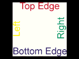
Figure 1: The original bitmap (on a black background).

Rendering 1:
The next example shows how an image can be tiled across the geometry by using mapping coordinates greater than 1.0. The X mapping coordinate for vertex 1 and vertex 2 are 2.0 (and the material tiling check box are enabled in the Materials Editor). This results in the image being repeated in the U direction twice as shown below. Note that it is only tiled once in V since the Y coordinates are still 1.0.

Figure 2:
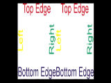
Rendering 2:
The next example shows how negative texture coordinates are used to reverse the way the image is mapped to the geometry. In the figure below, the X texture coordinates are -2.0 for vertex 1 and vertex 2. This results in the image be mirrored about the vertical axis of the map. It is also repeated twice since the coordinates are -2.0 and not -1.0.

Figure 3:
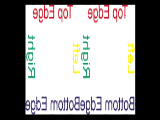
Rendering 3:
The next diagram shows how mapping coordinate greater than 0.0 start the image off at a offset within the image. Here the coordinates are the same as in example 1, except all the values have been shifted by 0.5 in X and 0.5 in Y. This results in the image being shifted on the geometry. Here again, tiling is on, so the pattern begins in the center of geometry, but is tiled and thus reappears from the left and bottom edges.

Figure 4:
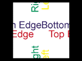
Rendering 4:
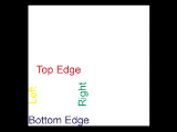
There is something special about UVW coordinates in the range of 0.0 to 1.0. If image tiling is turned off in the Materials Editor (the 'Tile' check box is unchecked for a certain direction), then the image will only appear where the texture coordinates are in this range. UV values outside the range 0.0 to 1.0 will not be mapped when tiling is off in that direction. This is shown in the diagram below. The material editor settings have tiling off in both the U and V directions, and the mapping coordinates are from [0.0 to 2.0]. Note that the image only appears where the mapping coordinates are in the range [0.0 to 1.0], i.e. the lower left corner.

Figure 5:
Rendering 5:
As mentioned above, users may alter the tiling, mirroring, angle, and offset settings from within the material. These controls adjust the position of the map relative to the mapping coordinates. In the figure shown below, the material controls have been used to add an additional transformation to the mapping shown above in figure 5. The texture coordinates stored with the geometry are just the same, but a U Offset of 0.5 and a V Offset of 0.5 were used to shift the map onto the center of the geometry. Additionally, a U tiling setting of 0.75 was used to 'stretch' the mapping in the U direction. Thus the image is no longer square, but is rather elongated in U. Rendering 6 below shows the resulting image.
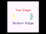
Rendering 6:
Developers may access all the users material transformation settings using the methods of class StdUVGen. The code shown above in the section Accessing Materials Properties sections shows how this is done.
Texture Mapping
This section provides a quick look at how the texture coordinates described above are applied to objects in 3ds max using the standard mapping methods (planar, cylindrical, spherical, etc.).
In general this is quite simple. Basically, the geometric vertices of the object being mapped are transformed into some space (another coordinate system) and then these transformed geometric coordinates become the texture coordinates. For example in a simple planar mapping, the geometric vertices are transformed into the coordinate system of the mapping icon. Once transformed, the X, Y geometric coordinates become the UV mapping coordinates. For a cylindrical mapping the same thing is done except instead of taking just the X, Y coordinates, they are further transformed into a cylindrical coordinate system. Then these values become the UV mapping coordinates.
In camera mapping, where the texture coordinates of an object are used to match a background image, the geometric coordinates are transformed into camera screen space, and then screen X, Y becomes the UV coordinates.
Face-Map Materials
There is another method of applying mapped materials that requires no application of mapping coordinates by the user whatsoever. In the Materials Editor, you can create a face-map material. When a face-map material is applied to an object, the map is automatically applied to each facet of the object. Below is the code used internally by 3ds max that computes the texture coordinates for face mapping:
static Point3 basic_tva[3] = {
Point3(0.0,0.0,0.0),Point3(1.0,0.0,0.0),Point3(1.0,1.0,0.0)};
static Point3 basic_tvb[3] = {
Point3(1.0,1.0,0.0),Point3(0.0,1.0,0.0),Point3(0.0,0.0,0.0)};
static int nextpt[3] = {1,2,0};
static int prevpt[3] = {2,0,1};
static void make_face_uv(Face *f, Point3 *tv) {
int na,nhid,i;
Point3 *basetv;
/* make the invisible edge be 2->0 */
nhid = 2;
if (!(f->flags&EDGE_A)) nhid=0;
else if (!(f->flags&EDGE_B)) nhid = 1;
else if (!(f->flags&EDGE_C)) nhid = 2;
na = 2-nhid;
basetv = (f->v[prevpt[nhid]]<f->v[nhid]) ? basic_tva : basic_tvb;
for (i=0; i<3; i++) {
tv[i] = basetv[na];
na = nextpt[na];
}
}
Bump Mapping in Procedural Textures
Bump mapping is a technique that enables a surface to appear wrinkled or dimpled without the need to model these depressions geometrically. Rather, the surface normal is perturbed according to information given in the 'bump map'. This results in variations to the smooth surface.
A 2D bump map is applied to the surface of an object. The space along the surface is called the UV space. The 2D bump map can be thought of as its own surface, where bright areas are hills and dark areas are valleys. On the surface then you can define a gradient, which can be thought of as the 'downhill' or 'uphill' directions. This gradient of values gives you a direction in UV space where you are going to perturb the surface normal. If you have a bump in a texture (a steep hill up for example) then you want to perturb the normal to make it look like there is a steep hill up there. Given the gradient in UV space, you need to figure out what direction in 3D (XYZ) space to perturb the normal that corresponds to that gradient in UV space. The bump basis vectors are used for this purpose. These are the vectors that represent the UVW axes of that texture in 3D. These are unit vectors that can be used to perturb the normal.
To understand how this is done, let's look at some sample code. The method responsible for returning the perturbed normal is Texmap::EvalNormalPerturb(). The code below happens to be from \MAXSDK\SAMPLES\MATERIALS\CHECKER.CPP but all the other 2D textures use a similar approach.
Point3 Checker::EvalNormalPerturb(ShadeContext& sc) {
Point3 dPdu, dPdv;
if (!sc.doMaps) return Point3(0,0,0);
if (gbufID) sc.SetGBufferID(gbufID);
uvGen->GetBumpDP(sc,dPdu,dPdv);
Point2 dM = uvGen->EvalDeriv(sc,&mysamp);
return dM.x*dPdu+dM.y*dPdv;
}
The first significant line related to bump mapping is:
uvGen->GetBumpDP(sc,dPdu,dPdv);
This method of UVGen gets the bump vectors. Developers can also get the bump vectors directly from the method ShadeContext::DPdUVW() although these would not be affected by the UVGen transformations. In our case, since all the coordinates are coming through UVGen, we must use GetBumpDP() since the UVGen has rotated things around -- it has transformed the bump vectors to a new position. Basically, the UVGen has rotated the UV space into another position locally. So again, this method gets the bump basis vectors, which are really the U and V axes in 3D space (unit vectors in the U direction and the V direction, but in 3D space).
The next line computes dM. This is the derivative of the function across the pixel. This is the rate of change of the function in the U direction (dM.x) and the V direction (dM.y). So for example, if this is a flat function, these will both be zero. If the function is increasing in U but is constant in V then the value in the U direction will correspond to how fast it is changing while V will still be zero. Thus, dM can be thought of as the gradient -- how fast things are changing up and down.
Point2 dM = uvGen->EvalDeriv(sc,&mysamp);
Next, we need to compute the perturbation to the normal. This can be thought of as a small vector that will be added to the end of the existing normal that will move it over a little bit. There are several ways to do this. The common textbook algorithm (Blinn's algorithm for bump mapping) is not used by the 3ds max textures. Rather, the calculation shown below was found to be simpler and faster with no visual difference. To compute the perturbation to apply to the normal the following code is used:
return dM.x*dPdu+dM.y*dPdv;
This takes the sum of the U component (dM.x) multiplied by the U basis vector (dPdu) and the V component (dM.y) multiplied by the basis vector in the V direction. This gives the change (perturbation) to the normal as a unit vector.
The result of EvalNormalPerturb(), the perturbation to apply to the surface normal, is used by 3ds max as follows: Outside the procedural texture, for example in the Standard material, the value returned is added on to the surface normal. Then the normal is re-normalized (made a unit vector again). This altered normal results in the surface appearing 'bumped' when rendered.
Assigning Materials to Nodes in the Scene
A developer may also wish to create materials and assign them to nodes in the scene. There are functions available for creating the standard 3ds max materials and textures such as Standard, Mult/Sub-Object, Bitmap texture, Composite texture, Mix, etc. These functions are not part of a class but are globally accessible (they are defined in \MAXSDK\INCLUDE\STDMAT.H).
StdMat *NewDefaultStdMat();
This function creates a new 3ds max Standard material. See Class StdMat.
MultiMtl *NewDefaultMultiMtl();
This function creates a new 3ds max Multi/Sub-Object material. See Class MultiMtl.
BitmapTex *NewDefaultBitmapTex();
This function creates a new 3ds max Bitmap texture. See Class BitmapTex.
MultiTex *NewDefaultCompositeTex();
This function creates a new 3ds max Composite texture. See Class MultiTex.
MultiTex *NewDefaultMixTex();
This function creates a new 3ds max Mix texture. See Class MultiTex.
MultiTex *NewDefaultTintTex();
This function creates a new 3ds max Tint texture. See Class MultiTex.
GradTex *NewDefaultGradTex();
This function creates a new 3ds max Gradient texture. See Class GradTex.
StdCubic *NewDefaultStdCubic();
This function creates a new 3ds max Reflect/Refract texture. See Class StdCubic.
StdMirror *NewDefaultStdMirror();
This function creates a new 3ds max Flat Mirror texture. See Class StdMirror.
StdFog *NewDefaultStdFog();
This function creates a new 3ds max Fog atmospheric effect. See Class StdFog.
Sample code using many of these functions is available in the 3D Studio DOS file import plug-in. This code may be found in \MAXSDK\SAMPLES\IMPEXP\3DSIMP.CPP.
The code below demonstrates how a 3ds max Standard material may be assigned to a mesh object. It assigns a material with Red Ambient and Diffuse settings to the first node in the current selection set.
void Sample::AssignMtl(Interface *ip)
{
if (! ip->GetSelNodeCount()) return; // Nothing to assign.
INode *node = ip->GetSelNode(0);
// Create a new Standard material.
StdMat *m = NewDefaultStdMat();
// Set its properties...
m->SetName(_T("Sample"));
m->SetAmbient(Color(1.0f,0.0f,0.0f),0); // Pure Red
m->SetDiffuse(Color(1.0f,0.0f,0.0f),0);
m->SetSpecular(Color(1.0f,1.0f,1.0f),0);
m->SetShininess(0.5f,0);
m->SetShinStr(.7f,0);
// Assign it to the node.
node->SetMtl(m);
ip->RedrawViews(ip->GetTime());
}
Editing Material or Texture Parameters in the Materials Editor
This section discusses the manner in which plug-in texture and materials manage their user interface in MAX. This is only a concern of developers creating plug-in materials or textures.
The way materials and texture maps handle their user interface is different than the way other plug-ins handle their UI in the command panel of MAX. For materials and textures, a developer derives a class from ParamDlg and implements its methods.
A method of MtlBase named CreateParamDlg() is called by the system when the material or texture is to be displayed in the material editor parameters area. This method is expected to create a new instance of a class derived from ParamDlg. The system then maintains the ParamDlg pointer. When the system needs to delete the memory associated with this instance it calls the method ParamDlg::DeleteThis().
Within the instance of the class derived from ParamDlg a developer can store any data needed to handle the user interface (for example, spinner control handles, window handles, etc.). The class will also need to have a pointer to the 'thing' that is being edited. This 'thing' is either a texture or the material.
As the user works with different materials in the materials editor, these materials have to put up their user interfaces. For example, if the user is editing a Standard material in one sample window, then selects another Standard material in another sample window, the user interface changes to reflect the new material settings. The user interface does not 'flash' however -- in other words the entire rollup page is not deleted and replaced. Rather the fields are simply updated to reflect the new values. What the system is doing is effectively 'passing off' the user interface from one material to another. Two methods of ParamDlg allow this to happen. These are SetThing() and GetThing().
When a system calls SetThing() it passes a pointer to a ReferenceTarget. This is the item that is being edited. So normally a developer would implement this method to store the item being edited (the 'thing') and update the user interface controls to reflect the state of the new 'thing'.
When the system calls GetThing(), the plug-in returns the 'thing' that is currently being edited.
As an example, consider the following code from the Checker texture map. Checker derives a class from ParamDlg and uses data members to store the data needed for its operation. A portion of this code is shown below:
class CheckerDlg: public ParamDlg {
public:
HWND hwmedit; // window handle of the materials editor dialog
IMtlParams *ip;
Checker *theTex; // current Checker being edited.
HWND hPanel; // Rollup pane
ISpinnerControl *blurSpin;
IColorSwatch *cs[2];
TimeValue curTime;
ParamDlg *uvGenDlg;
int isActive;
...
Note that CheckerDlg has a data member that is a pointer to an instance of Checker (theTex). This is where it stores the 'thing', i.e. the current Checker being edited. Shown below are Checker's implementations of GetThing() and SetThing().
ReferenceTarget* GetThing() { return (ReferenceTarget *)theTex; }
When the system calls GetThing(), Checker just returns the pointer to the item that is currently being edited.
void CheckerDlg::SetThing(ReferenceTarget *m) {
assert (m->ClassID()==checkerClassID);
assert (m->SuperClassID()==TEXMAP_CLASS_ID);
if (theTex) theTex->paramDlg = NULL;
theTex = (Checker *)m;
uvGenDlg->SetThing(theTex->uvGen);
if (theTex)
theTex->paramDlg = this;
LoadDialog(TRUE);
}
When the system calls SetThing(), Checker store the pointer to the item that is currently being edited into theTex. The Checker class itself maintains a pointer to the instance of ParamDlg that is handling the user interface. Note that Checker stores the this pointer (theTex->paramDlg = this;).
Also note that CheckerDlg maintains a pointer to a UVGen (UVGenDlg). UVGen is a class developers use to encapsulate the user interface for UV coordinates. This pointer is initialized in the CheckerDlg constructor as follows:
uvGenDlg = theTex->uvGen->CreateParamDlg(hwmedit, imp);
In the CheckerDlg implementation of SetThing() it also calls the SetThing() method on the uvGenDlg. This allows the UVGen to update its user interface in the dialog. These are the controls in the 'Coordinate' and 'Noise' rollups.
Pre-defined Categories of Texture Maps
Developers creating texture maps should use the text strings shown below to distinguish between the various types of maps so they can be separated in the Material/Map Browser.
TCHAR TEXMAP_CAT_2D[]; - 2D maps.
TCHAR TEXMAP_CAT_3D[]; - 3D maps.
TCHAR TEXMAP_CAT_COMP[]; - Composite.
TCHAR TEXMAP_CAT_COLMOD[]; - Color modifier.
TCHAR TEXMAP_CAT_ENV[]; - Environment.
The appropriate string should be returned by the ClassDesc::Category() method of the Texmap. For example:
const TCHAR* Category() { return TEXMAP_CAT_3D; }
See Class ClassDesc for more details on this method.
Miscellaneous Function and Macros for use with Materials
The following functions are not part of any class but are available for use by plug-ins.
Developers that have created a 3D Studio/DOS SXP and a corresponding 3ds max texture plug-in may want to have a look at Class Tex3D. It provides a way to have an instance of your 3ds max texture plug-in created automatically when the corresponding SXP is found in a 3DS file being imported (using the standard 3ds max 3DS importer).
Another handy materials related function is CombineMaterials(). This function combines the two specified materials into a multi-material.
Prototype:
Mtl *CombineMaterials(Mtl *mat1, Mtl *mat2, int &mat2Offset);
Remarks:
Implemented by the System.
This function is available in release 3.0 and later only.
This function combines the two specified materials into a multi-material. Either of the two input materials can themselves be multi materials.
Parameters:
Mtl *mat1
Points to the one of the source materials.
Mtl *mat2
Points to the other source material.
int &mat2Offset
The index of the first mat2 material in the combined material is returned here.
Return Value:
A pointer to the new multi-material.
The following function may be used to determine if the MtlBase pointer passed is a material (Mtl):
inline int IsMtl(MtlBase *m)
{ return m->SuperClassID()==MATERIAL_CLASS_ID; }
The following function may be used to determine if the MtlBase pointer passed is a texture (Texmap):
inline int IsTex(MtlBase *m)
{ return m->SuperClassID()==TEXMAP_CLASS_ID; }
The following functions return the intensity of the color passed:
static inline float Intens(const AColor& c)
{ return (c.r+c.g+c.b)/3.0f; }
static inline float Intens(const Color& c)
{ return (c.r+c.g+c.b)/3.0f; }
The following functions return default instances of several classes implemented by the system:
UVGen* GetNewDefaultUVGen();
XYZGen* GetNewDefaultXYZGen();
TextureOutput* GetNewDefaultTextureOutput();
Note the following typedef's used with materials and textures:
typedef MtlBase* MtlBaseHandle;
typedef Mtl* MtlHandle;
typedef Texmap* TexmapHandle;