Style Guidelines for Creating Pipeline-Friendly Meshes
See Also: Working with Meshes, Class MNMesh.
3ds max meshes allow the developer a great deal of flexibility. There are very few rules. Meshes can have holes in them, such as you get when deleting any face from a box or a sphere. They may be composed of separate, disconnected units, which may even self-intersect. A 'fan' of 10 faces can use the same edge, simply by using the same two vertices. A grid may be created which is simply a 2-D collection of points with one set of faces pointing up and another pointing down.
However, not all of the possible meshes are appropriate for operations that may be done to them later in the 3ds max pipeline. For instance, the 3ds max Boolean, like any other Boolean, regards meshes as the outside boundary of solid objects. A Boolean intersection, for instance, is defined by the intersection of the volumes contained by the two operands. A mesh with a hole in it, such as the teapot, contains no volume, and therefore produces surprising results in Boolean.
Furthermore, Boolean, like several other compound objects and modifiers, converts meshes internally into MNMeshes. The MNMesh winged-edge structure can only handle 2 faces on a single edge, so the 'fan' described above gives it some difficulty. A mesh that doesn’t gracefully convert to an MNMesh won’t always behave as expected in MeshSmooth, Tesselate, ShapeMerge, Connect, Boolean, Slice, and possibly many more to come.
Also, if a mesh is not constructed in a straightforward manner, the user may experience some difficulty working with it in modifiers such as Edit Mesh. Of course, the user can construct very strange meshes themselves in Edit or Editable Mesh, but it’s best if parametric objects and modifiers avoid introducing this sort of complexity when it isn’t needed.
To that end, the following style guidelines for creating pipeline-friendly meshes in 3ds max are presented. None of these are hard-and-fast rules, but the more you are able to follow, the more flexible your mesh will be within the 3ds max environment.
1. Reference each edge at most once in each direction.
3ds max meshes don’t really have edges, so what this means is that if you use the vertices (a,b) in a face, you should only have one other face that uses both of these vertices, and it should reference them in the other direction (b,a). This other face is the 'other side' of the edge (a,b). If the same edge is used more than twice, or more than once in the same direction, MeshSmooth and other MNMesh-based effects have to compensate by duplicating the vertices used in the edge, once for each extra face using this edge.
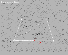
Figure 1A: Typical use of an edge
Face 0, which has vertices (0,3,2), uses the hidden edge in the (0,3) direction. Face 1, with vertices (0,1,3), uses the same edge in the (3,0) direction. The other edges are '1-sided', since there’s no face on their other side.
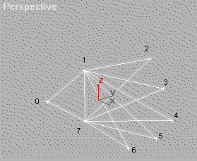
Figure 1B: Overuse of an edge
The face on the left uses the central edge in the (7,1) direction; the other 5 use it in the (1,7) direction. This can be inconvenient for the user and for many pipeline modifiers. Also, it generally doesn’t respond well to smoothing groups.
Another situation in which edges are referenced too many times is when a zero-thickness mesh is constructed, with faces on both sides.
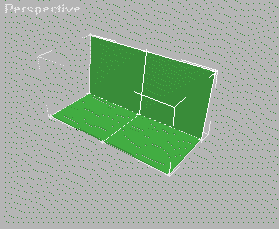
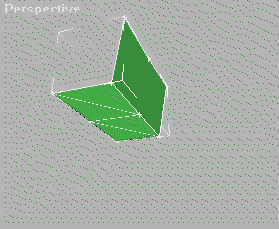
The above two views show the same zero-thickness mesh, with 9 points, that has faces representing both the front and back. The edges connecting the outside to the central point are used twice by front-facing faces and twice by back-facing edges. This also can cause problems in the pipeline. Additionally, some systems may not display edges properly, as shown above at right: the edge connecting the top middle and base middle vertices should be visible, but doesn’t show up because both the front-facing and back-facing faces have the same Z-depth.
2. Avoid self-intersection
For an example of self-intersecting meshes, we need look no further than the standard 3ds max primitive Teapot. Each of the four Teapot components is a separate mesh element, but the handle and spout elements both intersect the main body. Even if this mesh is closed with the CapHoles modifier, it causes trouble for Booleans because once again, what is 'inside' and what is 'outside' the teapot isn’t very well defined.
For an alternative to self-intersection, when (as in the teapot) computing the proper, connected result would be taxing, you may want to use the Boolean itself within the SDK. If separate mesh elements are closed and otherwise acceptable to Boolean, you can just Union them together. Boolean is a bit slow, however, and there are still some known cases where it actually produces an open result. See the MakeBoolean method in class MNMesh (MNMesh Boolean Operations).
3. Avoid creating faces with vertices located at the same place.
A face referencing the same vertex twice, or two different vertices located in the same place, makes no contribution to your mesh and can interfere with display and rendering. Also, it confuses algorithms that traverse faces, such as ShapeMerge or Editable Mesh’s new Cut function. Finally, Edit Mesh users can find it very frustrating to have to sort through multiple vertices at the same location in order to move the one they want.
4. Try not to 'bridge' separate mesh components with a single vertex.
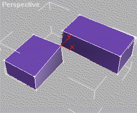
The above two boxes share a single vertex, which is selected. Such vertices are split by MNMesh conversions. MNMesh effects deal with such vertices adequately, but the duplication is occasionally a surprise.
5. If a mesh looks like a single element, it probably should be.
A user shouldn’t be able to take what looks like a single object apart by moving 'element' selections in Edit Mesh. If a model looks like a box, it shouldn’t behave like a collection of 6 separate faces. This will give the user more reasonable results not only in modifiers like MeshSmooth, but also when they edit the object in Edit Mesh.
6. Whenever convenient, close your meshes.
A 'closed' mesh is one in which every edge has exactly two faces: one on each side. Closed meshes represent 3-dimensional objects. Open meshes are mere shells. Closed objects respond well to Boolean operations; open ones can’t, since there’s no way for the Boolean to know which parts of operand A are supposed to be 'inside' operand B, and vice versa. Closed meshes have measurable volume; open ones do not.
This style point is less important than the others, because users are used to dealing with it. Any user who has models in Editable Mesh, for instance, deletes faces and constructs new ones all the time. However, avoid catching users off-guard: try not to leave tiny holes that can’t be seen, say by putting open edges very close to each other. Users may not see them, but any hole will cause problems in pipeline effects that depend on solid, closed meshes, and may affect rendering adversely.