Geometry Pipeline System
See Also: Class ModContext, Class ObjectState, Class LocalModData, Class IDerivedObject, Class Object, Class INode, List of Channel Bits, Class GeomPipelineEnumProc.
Sub-Topics
The following hyperlinks jump to the beginning of sub-topics within this section:
Developer Access to the Pipeline
The Pipeline and the INode TM Methods
Objects Flowing Through the Pipeline
Overview
An understanding of the geometric pipeline system is important for developers creating plug-ins that deal with geometry in the scene. This section describes the pipeline system. A pipeline is the system used by 3ds max that allows a node in the scene to be altered, perhaps repeatedly, through the application of modifiers.
At the beginning of a pipeline is the Base Object. This is a procedural object or just a simple mesh. At the end of a pipeline is the world space state of the object. This world space state is what appears in the 3D viewports and is rendered.
For the system to evaluate the state of the object at the end of the pipeline, it must apply each modification along the way, from beginning to end. As an example, say a user creates a procedural cylinder in the scene, applies a Bend modifier to it, and then applies a Taper modifier to it. As the system evaluates this pipeline, it starts with the state of the cylinder object. As this object state moves along the pipeline, it encounters the Bend modifier. The system asks the Bend modifier to apply its deformation to the object state. The result of this operation is passed as the source into the Taper modifier. The Taper then applies its deformation. The result of this operation is passed to the system which translates the result into world space, and the state of the node in the scene is complete.
To maximize the speed that the system can evaluate the state of a node, the system maintains a World Space Cache for each node in the scene. This world space cache is the result of the node's pipeline. It reflects the state of the object in world space after everything has been applied to it. Along with the cache, the system maintains a Validity Interval. The validity interval indicates the period of time over which the cache accurately reflects the state of the node.
Whenever a node needs to perform an operation, such as display itself at a certain time, the system checks the validity interval at that time to see if the cache is valid. If it is, the operation is performed using the cached representation. If it is not, the pipeline is evaluated and the cache is made valid at that time. The validity interval is also updated to reflect the new cache. The operation is then performed.
As an additional mechanism to speed up processing, a pipeline is broken up into Channels. Channels allow modifiers to only alter certain portions of the object. For example, there is a separate channel for geometry (i.e. the vertices of the object). If a modifier only affects the vertices and nothing else, the system has considerably less work to do than if it had to reevaluate the entire state of the object including its face structure, UV coordinates, material assignments, etc. For example, the Bend modifier only affects the geometry channel; all the other channels do not require evaluation.
There are separate channels for geometry (vertices), topology (face or polygon structures), texture vertices (UV coordinates), sub-object selection, level of selection, and display control. These separate channels allow the cache system of 3ds max to be more sophisticated. Instead of just caching one global state for the object, it can cache separate portions of it based on the channels.
Pipeline Details
This section discusses the details of the 3ds max pipeline architecture. The concepts of Base Objects, Derived Objects, and World Space Derived Objects are presented. The ModContext, ModApp, and ObjectState are also explained.
The diagram below (Figure 1) shows the simple pipeline of a Cylinder in the scene. Each node in the scene has a reference to an object. In this case the node's object reference points directly to the Base Object. It is the flow of these object references that represent the pipeline. In this case it's the flow from the node's object reference to the procedural cylinder object that stores the creation parameters.
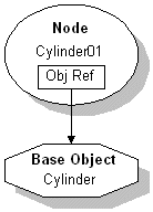
Figure 1.
In 3ds max objects can be instanced. This means that more than one node can point to the same object reference. Figure 2 below shows two pipelines. In this case there is a Cylinder and an instanced copy of it. Note how the object reference of the instanced copy points to the same Base Object as the original. If the creation parameters of the Cylinder are changed, both nodes will change in the scene since they both point at the same Base Object which stores the creation parameters.
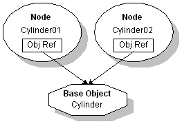
Figure 2.
3ds max supports the application of one or more modifiers to alter the pipeline in some way. Figure 3 below shows the pipeline resulting from applying a Bend object space modifier to a Cylinder. When a modifier is first applied, a new Derived Object is inserted into the node's pipeline.
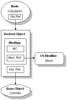
Figure 3.
This arrangement would appear in MAX's modifier stack as follows:
Bend
----------
Cylinder
This indicates that the Base Object of the pipeline is the Cylinder. The ---------- indicates the start of a Derived Object. The Bend is the modifier referenced by this Derived Object.
A Derived Object consists of one or more applications of modifiers followed by a reference to another object. This other object may be a Base Object or another Derived Object. In Figure 3 above, the Derived Object has a single application of a modifier. This application of a modifier is referred to as a ModApp. The ModApp primarily consists of a reference to a modifier -- in this case the Bend. Note that the modifier does not sit within the pipeline, but is rather referenced by the ModApp within the pipeline.
In addition to the modifier reference, the ModApp contains an instance of the class ModContext. In Figure 3 and those that follow, the ModContext is represented by a box labeled 'MC'. The ModContext stores information about the space the modifier was applied in, and allows a modifier to store data that it needs for its operation.
Specifically, the ModContext stores three items shown in Figure 4 and described below:
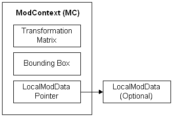
Figure 4.
 The Transformation Matrix. This matrix represents the space the modifier was applied in. The modifier plug-in uses this matrix when it deforms an object. The plug-in modifier first transforms the points with this matrix. Next it applies its own deformation. Then it transforms the points back through the inverse of this transformation matrix.
 The Bounding Box of the Deformation. This represents the scale of the modifier. For a single object it is the bounding box of the object. If the modifier is being applied to a sub-object selection it represents the bounding box of the sub-object selection. If the modifier is being applied to a selection set of objects (and the user interface 'Use Pivot Points' checkbox is off), then this is the bounding box of the entire selection set. For a selection set of objects the bounding box is constant. In the case of a single object, the bounding box is not constant. For example, if the user applies a 90 degree bend to a cylinder, then changes the height of the cylinder, one would want the cylinder to still be bent 90 degrees. If the bounding box did not adapt, the cylinder would appear to move through the bend causing the bend angle to be incorrect.
 A pointer to an instance of a class derived from LocalModData. This is the part of the ModContext that the plug-in developer controls. It is the place where a modifier may store application-specific data. The LocalModData class has two methods the derived class must implement. One is a Clone procedure so the system can copy a ModContext. The second is a virtual destructor so the derived class can be properly deleted.
More than one modifier may be applied to an object. Figure 5 below shows the previous bent cylinder with an additional Taper modifier applied.
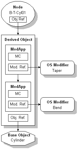
Figure 5.
In this case a new ModApp is inserted into the existing Derived Object. The modifier reference of the new ModApp points to the Taper modifier.
3ds max also allows Reference Copies of items in the scene. Note: the use of the term 'Reference' here is from the 3ds max user interface definition of reference -- not the C++ reference or the 3ds max dependency reference meanings.
When a Reference Copy is made, a new Derived Object is inserted into the item's pipeline. Modifiers applied to the Reference Copy will have their ModApps inserted into the new Derived Object. You can see this graphically illustrated in Figure 6. This diagram shows the result of a bent cylinder being Reference Copied and having a Taper modifier applied. Note that the object reference of the new Derived Object points to the original Derived Object.
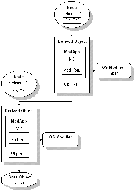
Figure 6.
The modifier stack for Cylinder02 in Figure 6 would appear as:
Taper
----------
Bend
----------
Cylinder
Note the two occurrences of the ---------- indicating that two Derived Objects are in use. The original one points to the Bend while the new one points to the Taper.
Instanced Modifiers
An instance of the ModApp class exist in addition to the modifier because the plug-in modifier itself may be instanced (used by several objects). When the user applies a modifier to more than one object, one new instance of the modifier's class is created and shared amongst the objects. Each object that the modifier is applied to gets a new ModApp inserted into its pipeline. These ModApps then reference the same modifier.
In the screen image and diagram below (Figures 7 and 8), the user has selected two independent Cylinders in the scene, checked the 'Use Pivot Points' box, and applied a Bend modifier.
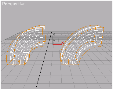
Figure 7.
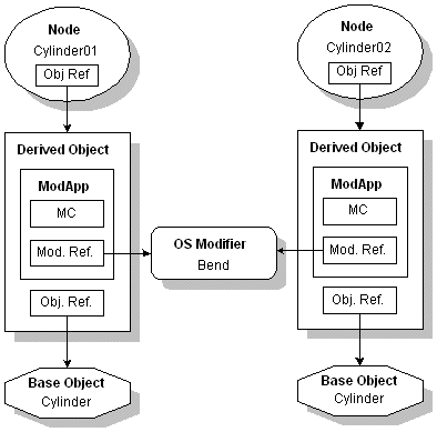
Figure 8.
Note that each cylinder has its own Derived Object. The modifier reference of each ModApp points to the same instanced modifier however. The ModApp also stores the ModContext (labeled 'MC' in the diagrams). One data member of this ModContext is the bounding box of the deformation. Because the 'Use Pivot Points' button was checked at the time the bend was applied, each bounding box stored in the ModContext is the size of each cylinder alone. Additionally, the transformation matrix of each ModContext reflects that the bend is to be applied to each cylinder in its own space. The result is the bend is applied locally and independently to each cylinder.
Contrast this with the following case. In the screen capture of Figure 9 the user applied the Bend modifier to the cylinders as follows: First the independent cylinders were selected. Then the 'Use Pivot Points' button was un-checked. Then the Bend modifier was applied. This means the bend will be applied to the entire selection set as a whole. Note that the cylinders are bent about a common center.
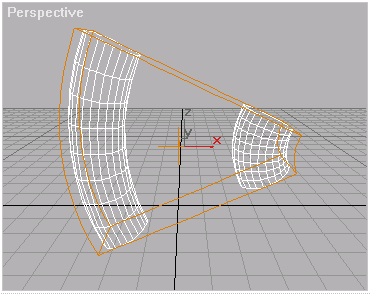
Figure 9.
In this case the bend is applied relative to the bounding box of both cylinders. Thus the bounding box of the ModContexts are the same for each cylinder. Note what happens if one cylinder is moved away from the other in the scene. The Modifer is selected so the gizmo shows the bounding box graphically. The bounding box remains the size of both even when the objects no longer share the same world space relationship.
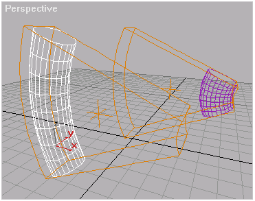
Figure 10.
The separation of the ModApps from the Modifier allow this flexibility. The bounding box stored with the ModContext of the ModApp represents the scale of the application of the modifier. The transformation matrix of the ModContext represents the space the modifier was applied in. The instanced modifier just uses this information to properly modify each input object.
Space Warps (World Space Modifiers) in the Pipeline
This section discusses the pipeline of items with World Space Modifiers applied. Below is a diagram of a Cylinder and a Ripple Space Warp before the Cylinder has been bound to the space warp.
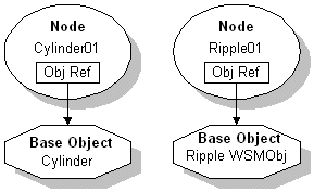
Figure 11.
The following diagram shows the pipeline of the Cylinder after it has been bound to the Ripple Space Warp.
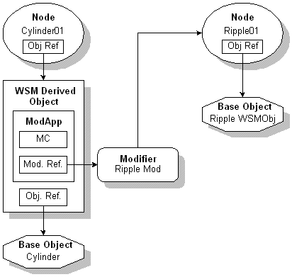
Figure 12.
The modifier stack for this condition would appear as follows:
Ripple Binding
==========
Cylinder
The Cylinder is the Base Object. The ========== represents the beginning of a WSM Derived Object. The Ripple Binding is the actual application of the world space modifier.
When the Cylinder is bound to the Ripple a new WSM Derived Object is inserted into the Cylinder's pipeline. The WSM Derived Object is similar to the Derived Objects that hold object space modifier ModApps except that these are contained in a specific node (WSM Derived Object is in fact the exact same class as Derived Object except for the ClassID()). Since they are associated with a specific node, they cannot be instanced.
The modifier reference of the ModApp points to a newly-created WSM Modifier. This WSM Modifier usually has a references to the node in the scene. In this case it is to the Ripple01 node. This reference is used to retrieve the position of the node (from the node's world space transformation matrix). It uses this matrix to transform the points of the object it is deforming into the space of the WSM object where it actually performs the deformation. For additional information on Space Warp plug-ins see the Advanced Topics section Space Warp Plug-Ins.
ObjectState Details
The object state is the structure that flows up the pipeline. When the Object::Eval() method is called on an object or a derived object, it returns an ObjectState. This is passed from one object reference to the next. The ObjectState contains these elements:
 A pointer to the object in the pipeline. A modifier will often refer to the object in the pipeline using this pointer. The object pointer is a public data member and is defined as: Object *obj;
 A matrix. If an object cannot convert itself to a deformable type, 3ds max deforms a matrix instead. After the matrix is deformed, it is converted back into an = 4) BSPSPopupOnMouseOver(event);;">orthonormal matrix using an iterative process that 'averages' the axis. All objects are supposed to be able to convert themselves to TriObjects (which are deformable) so in general this is not used. However in the case of cameras and lights it doesn't make sense to convert them to TriObjects so this is how they are deformed. You can see an example of this by binding a camera to a space warp like ripple. The camera will bounce up and down as it is 'deformed' by the space warp.
 Flags for channels that are Boolean type. Developers do not need to be concerned with these flags.
 A material index. This is no longer used.
See Class ObjectState for details on the methods dealing with the ObjectState.
Developer Access to the Pipeline
This section discusses how a developer can access and work with the results of the pipeline.
There is an API available to retrieve the result of a node's pipeline. This is INode::EvalWorldState().
Prototype:
virtual const ObjectState& EvalWorldState(TimeValue time,BOOL evalHidden=TRUE)=0;
This returns the result of the node's pipeline just as it appears in the scene. This may not return an object that a developer has a reference to -- it may just be an object that has flowed down the pipeline. For example, if there is a Cylinder in the scene that has a Bend and Taper applied, EvalWorldState() would return an ObjectState containing a TriObject. This is the result of the cylinder turning into a TriObject and being bent and tapered. See Class INode.
If a developer needs to access the object that the node in the scene references, then the method INode::GetObjectRef() should be used instead. See INode - Object Reference Methods.
Class IDerivedObject also allows a developer to create derived objects and add and delete modifiers. To access the pipeline of a node in the scene first retrieve the object reference using INode::GetOjbectRef(). Given this Object pointer check its SuperClassID to see if it is GEN_DERIVOB_CLASS_ID. If it is, you can cast it to an IDerivedObject. See Class IDerivedObject for more details.
Channel Details
Channels allow modifiers to only alter certain portions of the object. The pipeline is divided into the following channels:
Modifiers have the option of only modifying specific channels. The main purpose of this is to allow MAX's caching system to be more sophisticated. Individual caches can be constructed for different channels at different points along the pipeline. So for example, if the texture coordinate portion of the pipeline changes, and the geometric portion of the pipeline is cached, the geometry portion won't need to be reevaluated. This means that modifiers that only depend on geometry may not need to be reevaluated.
It is up to the object to define the meaning of the channels. Take the TOPO_CHANNEL for example. For a TriObject the topology is the face structure, the materials, and the smoothing information. For a SplineShape the topology is undefined. This is because a SplineShape is essentially just an array of points and has no topology.
Data Flow in the Pipeline - An Example
This section presents a detailed look at the flow of the pipeline from the Base Object to the resulting World Space Cache. This includes the derived objects of the object space portion of the pipeline, the application of the node's transform controller, and through the world space portion of the pipeline.
Figure 13 below is a diagram showing a procedural Cylinder with a Bend modifier applied, and bound to a Ripple space warp.
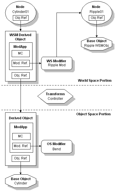
Figure 13.
The data flow in the pipeline follows the Object References. In the example above, the Cylinder01 Node has an Object Reference pointing to the WSM Derived Object. Its Object Reference points to the Derived Object. Its Object Reference points to the Cylinder Base Object. This is the path the data follows as it moves along the pipeline.
The actual object that flows between these references is an ObjectState. This ObjectState is the result of the Object::Eval() method being called on the Object Reference. Below is a description of the flow of this ObjectState along the pipeline starting at the procedural cylinder base object.
This pipeline starts at the Base Object -- the procedural Cylinder. The system asks the cylinder to evaluate itself. In the cylinder's implementation of Object::Eval(), it simply returns itself ( return ObjectState(this); ). It returns this ObjectState to the next Object Reference in the pipeline. This is the Object Reference of the Derived Object.
The Derived Object sends this ObjectState through each of its ModApps. In this example, the only ModApp is for the Bend Modifier. The Bend requires Deformable objects (it indicates this in its implementation of Modifier::InputType()). The ModApp handles converting the object to the appropriate type for the Modifier. The cylinder is asked to convert itself to a Deformable object. It does this in its implementation of Object::ConvertToType() by creating a new TriObject and setting the TriObject's mesh pointer to point at the cylinder's triangle mesh.
This Deformable TriObject is then sent through the Bend Modifier. The Bend is passed the ModApp's ModContext as an argument to its Modifier::ModifyObject() method. The Bend first modifies the points of the TriObject using the transformation matrix of the ModContext. This puts the object into the space the modifier was applied in. Next the Bend applies its deformation to the points (it bends them). Then the Bend modifies the points of the TriObject by the inverse of the ModContext transformation matrix. This restores the object, excepting it now has the bend effect applied.
At this point, the Derived Object returns the result to the next Object Reference in the pipeline. In this case the result is a TriObject that has been bent. It is returned to the Object Reference of a World Space Derived Object.
This juncture between the Derived Object and the World Space Modifier Derived Object is where the pipeline crosses from object space to world space. At this point the result of the node's transform controller, and the object offset transformation are put into the pipeline. For more details on these various TMs see the Advanced Topics section on Node and Object Offset Transformations.
To understand how the node's transform controller and the object offset transformation are put into the ObjectState we need to take a look at the ObjectState TM. There is a TM that is part of the ObjectState that flows up the pipeline. This TM starts as the identity matrix. The first thing that happens is this TM goes through the object space pipeline. At this time, any modifiers that need to be applied to it are applied. In most cases no modifiers are applied. However, if the object flowing through the pipeline is Deformable but has no points to deform (such as a camera), then modifiers acting on Deformables may be applied to it. This is because cameras are deformable, but don't have 'points' to deform (i.e. there is no 'mesh' associated with a camera). Since there are no points, this matrix is deformed instead.
At the end of the object space portion of the pipeline, out comes the ObjectState and its TM. Usually this TM is the identity, but at times (like with the camera) it is not.
Now the node's transform controller TM must be taken into account. The transform controller's TM is the result of taking the node's parent's TM, and passing it into the transform controller's Control::GetValue() method. The controller applies its relative effect to this matrix, and the result is the Node TM.
To the Node TM, the object offset transformation is applied. This result is then multiplied by the ObjectState TM that resulted from the object space portion of the pipeline. This resulting matrix is then stored back in the ObjectState TM. Note that this TM is not applied to the object yet -- it is only carried by the ObjectState.
At this point we have the node's transform controller and the object offset transformation stored in the ObjectState TM.
Now comes the world space portion of the pipeline and the world space modifiers -- we've reached the first ModApp of the WSM Derived Object. The first World Space Modifier transforms the object's points by this ObjectState TM. It does this because it does its deformation in world space, and applying the ObjectState TM puts the object into world space. This happens automatically for deformables. If the TM does not get applied to the object (for example for a camera) the TM will continue to get deformed by the world space modifiers. As soon as this TM is applied to the object points, the TM gets set to the identity matrix. At this time, the points of the object have been transformed into world space.
Next the ObjectState is passed to the Ripple Modifier for it to apply its effect. The Ripple modifier has a reference to the Ripple Object Node in the scene. It uses this reference to get the Object TM of the Ripple Node. It needs this because this is the space it is going to apply the ripple effect in. The Ripple Modifier also uses its reference to the Ripple Node to get the parameters of the Ripple WSM Object.
The Ripple Modifier uses this data, and applies its ripple affect. The result at this point is a TriObject with the Bend and Ripple applied. This ObjectState is returned to the next Object Reference in the pipeline. This is the Object Reference of the node in the scene.
The node maintains an ObjectState that is effectively the world space cache. This world space cache is the storage for the result of the pipeline. Associated with this cache is a validity interval. When the system needs the result of a node's pipeline, it checks to see if the validity interval of the cache is valid. If it is, the cached representation is used. If it is not, the pipeline is evaluated and the cache is made valid. The validity interval is updated, and the cached ObjectState is returned.
The Pipeline and the INode TM Methods
This section discusses the INode methods GetObjectTM(), GetObjTMBeforeWSM() and GetObjTMAfterWSM() and their relationship to the pipeline.
The INode::GetObjectTM() method returns a matrix that is used to transform the points of the object from object space to world space. Let's look at an example of how this method is used. Consider how the cylinder node is drawn in the scene. The cylinder draws itself in its BaseObject::Display() method. Into this method is passed an INode pointer. What the implementation of Display()does is call INode::GetObjectTM(). This method returns the matrix that is used to transform the points of the object from object space to world space. The Display() method then takes the matrix returned from GetObjectTM() and sets it into the graphics window (using GraphicsWindow::setTransform()). In this way, when the object starts drawing points in object space, they will be transformed with this matrix. This puts them into world space as they are drawn.
Below is the code from the SimpleObject implementation of BaseObject::Display(). This is the code that the cylinder uses to draw itself. Note the GetObjectTM(t) and setTransform(mat) calls.
int SimpleObject::Display(TimeValue t, INode* inode,
ViewExp *vpt, int flags)
{
if (!OKtoDisplay(t)) return 0;
GraphicsWindow *gw = vpt->getGW();
Matrix3 mat = inode->GetObjectTM(t);
UpdateMesh(t); // UpdateMesh just calls BuildMesh() if req'd at time t.
gw->setTransform(mat);
mesh.render(gw, inode->Mtls(),
(flags&USE_DAMAGE_RECT) ? &vpt->GetDammageRect() : NULL,
COMP_ALL, inode->NumMtls());
return(0);
}
There is a case when world space modifiers are applied to an object where the points of the object may have already been transformed into world space. If a world space modifier has been applied, the points of the object may have already been transformed into world space and then deformed by the world space modifier. With the bent, rippled, cylinder example above, this is exactly what has happened. When the ripple space warp was applied, the points of the object were transformed into world space. In this case, the points should not be transformed into world space again when they are drawn (since they were already by the space warp). The problem is, the object does not know if it has been transformed into world space or not.
The way 3ds max handles this situation is by storing some state information with the node. Before the system calls Display(), HitTest(), etc. on the object it sets a flag. The flag indicates if the object has already been transformed into world space. The GetObjectTM() method looks at this flag to determine the proper matrix to return. In this way, when GetObjectTM() is called, it returns the matrix the object needs to be multiplied by in order to get into world space. If the object is already in world space it will return the identity matrix. If it's not in world space, it will return the matrix to get it there. So all any objects need to do in their Display() methods is call GetObjectTM() and use whatever matrix is returned.
There may be times when a developer needs to access the full object TM regardless of whether the points of the object have been transformed into world space already. For example, if a developer was creating a utility plug-in to align two objects. In this case, the developer would need to get the full object TM including the NodeTM and the object offset transformation. It would not matter if the points of the object had already been transformed into world space, the TM is what matters. In this case GetObjectTM() would not work. This is because it returns the identity matrix if the object is already in world space.
To solve this problem 3ds max provides two other INode methods that may be used.
GetObjTMBeforeWSM()
This method explicitly gets the full NodeTM and object-offset transformation affect before the affect of any world space modifiers.
GetObjTMAfterWSM().
This method explicitly gets the full NodeTM and object-offset transformation and world space modifier affect unless the points of the object have already been transformed into world space in which case it will return the identity matrix.
Using these methods a developer has complete access to any transformation matrix they require. Below is a code example that uses all these methods. This function computes the bounding box of the first object in the current selection set at the current time. It removes anything but scaling from the Object TM. In this way rotation of the node will not affect the bounding box.
To do this we first need to determine if the object is in world space or in object space. Since we are after the object space bounding box (and will later apply scaling) we need to convert the TM back into object space if it is in world space. To check if the object is in world space we call GetObjTMAfterWSM(). If this matrix is the identity we know we are in world space. This is because when the points of the object get transformed by the ObjectState TM to put them into world space the ObjectState TM is set to the identity. Therefore if the matrix is the identity we are in world space.
If the object is in world space we need to compute the object space TM. We can do this by taking the inverse of the world space TM.
If the object is not in world space we just need to get its object TM by calling GetObjectTM().
Once we have the object space TM we want to extract just the scaling portion of the matrix. 3ds max provides a set of APIs that make this easy. This is done by calling decomp_affine(). This function decomposes a matrix into its translation, rotation and scaling components. See Structure AffineParts for more details.
Once we have the scaling portion of the matrix we can get the bounding box and apply the scaling by calling GetDeformBBox().
void Utility::ComputeBBox(Interface *ip) {
if (ip->GetSelNodeCount()) {
INode *node = ip->GetSelNode(0);
Box3 box; // The computed box
Matrix3 mat; // The Object TM
Matrix3 sclMat(1); // This will be used to apply the scaling
// Get the result of the pipeline at the current time
TimeValue t = ip->GetTime();
Object *obj = node->EvalWorldState(t).obj;
// Determine if the object is in world space or object space
// so we can get the correct TM. We can check this by getting
// the Object TM after the world space modifiers have been
// applied. It the matrix returned is the identity matrix the
// points of the object have been transformed into world space.
if (node->GetObjTMAfterWSM(t).IsIdentity()) {
// It's in world space, so put it back into object
// space. We can do this by computing the inverse
// of the matrix returned before any world space
// modifiers were applied.
mat = Inverse(node->GetObjTMBeforeWSM(t));
}
else {
// It's in object space, get the Object TM.
mat = node->GetObjectTM(t);
}
// Extract just the scaling part from the TM
AffineParts parts;
decomp_affine(mat, &parts);
ApplyScaling(sclMat, ScaleValue(parts.k*parts.f, parts.u));
// Get the bound box, and affect it by just
// the scaling portion
obj->GetDeformBBox(t, box, &sclMat);
// Show the size and frame number
float sx = box.pmax.x-box.pmin.x;
float sy = box.pmax.y-box.pmin.y;
float sz = box.pmax.z-box.pmin.z;
TSTR title;
title.printf(_T("Result at frame %d"),
t/GetTicksPerFrame());
TSTR buf;
buf.printf(_T("The size is: (%.1f, %.1f, %.1f)"), sx, sy, sz);
MessageBox(NULL, buf, title, MB_ICONINFORMATION|MB_OK);
}
}
A Note About Caching
The full details of the 3ds max pipeline cache system are beyond what a developer needs to understand to effectively work with the pipeline. There is however one detail that may be useful for a Modifier that is being adjusted interactively.
While a modifier is being edited, in its implementation of LocalValidity(), it can return NEVER. This forces a cache to be built after the previous modifier. For example, the SimpleMod class does this. The pipeline will try to put a cache after something that is relatively constant but before something that is changing a lot. If a modifier for its local validity starts returning NEVER, this will cause a cache to be created before it. This is useful if a modifier is being edited interactively. In this way, the system does not have to evaluate the whole pipeline. This can considerably improve the interactivity.
After the modifier is done being edited, if the modifier is not animated, there is no need to have a cache before it. Therefore after the modifier is done being edited, it can stop returning NEVER for LocalValidity(). Below is a code fragment from the SimpleMod implementation of LocalValidity() where this is being done:
Interval SimpleMod::LocalValidity(TimeValue t)
{
// If we are being edited, return NEVER to forces a cache to
// be built after previous modifier.
if (TestAFlag(A_MOD_BEING_EDITED))
return NEVER;
...
Modifier Stack Branching
Compound objects such as the boolean object and the lofter can actually cause the pipeline to branch. See the advanced topics section on Modifier Stack Branching for the details on the methods a compound object uses to implement branching in the pipeline.
Objects Flowing through the Pipeline
Certain plug-in objects flow through the pipeline. Examples are both the TriObject and the PatchObject. Most plug-ins do not however because they convert themselves to TriObjects or PatchObjects and these objects flow through the pipeline. For developers creating objects that flow through the pipeline there are some pipeline concepts and specific methods that must be understood. These are discussed in this section.
Most of these methods relate to minimizing the amount of overhead present within the system when the object is flowing through the pipeline. To be as efficient as possible the system will try not to create any extra copies of the object flowing down the pipeline. Additionally, the object is broken into channels and the individual channel copying is kept to a minimum.
To accomplish this, the system uses a set of 'locks' that indicate when it is not okay to free memory or modify the objects. The object lock and channel lock methods are implemented and called by the system. The plug-in developer implements methods to maintain validity intervals for the channels, create new copies of channels as needed, and free the memory associated with channels that are no longer needed. Again, the main purpose of this is to minimize the overhead of the object flowing down the pipeline.
Every object has what is referred to as its "shell". The shell has channels within it. Example channels are the geometry channel named GEOM_CHANNEL (typically an array of vertices) or the topology channel named TOPO_CHANNEL (typically an array of faces). Some channels are always present in the shell. For example the SUBSEL_TYPE_CHANNEL, SELECT_CHANNEL and DISP_ATTRIB_CHANNEL state channel are each just a single value. These are not allocated or de-allocated dynamically, and are always present. Other channels like the GEOM_CHANNEL, TOPO_CHANNEL, and TEXMAP_CHANNEL are allocated dynamically so the system tries to not have extra copies of them when possible.
The following methods from class Object deal with the state of the shell. These methods are implemented and called by the system.
void LockObject()
This method locks the object as a whole.
void UnlockObject()
This method unlocks the object as a whole.
int IsObjectLocked()
Returns nonzero if the object is locked; otherwise 0.
If the shell is locked then it should not be deleted by the pipeline. For example, a sphere in the pipeline will be locked. This is because it exists in the scene and thus should not be deleted. If a bend modifier was applied to the sphere, then the sphere would convert itself to a TriObject. This TriObject is flowing down the pipeline and is just a temporary object. This object will be unlocked meaning that it may be deleted. This is true unless a ModApp decides to cache it. In this case it will become locked because the ModApp has taken ownership of it and therefore it should not be deleted. Note that these methods are implemented and called by the system and not the plug-in object. They simply manipulate a private data member inside the Object class.
There is a related topic to discuss -- channel locking. This is not the locking of the object as a whole (as described above) but rather the locking of only certain channels within the object. For example, a ModApp may have the geometry channel cached (say it has an array of vertices cached somewhere in the pipeline). When the system is evaluating this pipeline, if it notices a certain channel it requires is cached, instead of evaluating the rest of the pipeline, it will use the cache. It will do what is called a shallow copy of the cached channel into the object going down the pipeline. This is just copying the pointer to the cached channel into the object flowing down the pipeline. So essentially there are two TriObjects whose geometry channels are both pointing to the same array of vertices. This reduces the memory overhead required because instead of copying the whole array of vertices there are essentially two meshes that are sharing the same block of memory. Again this is referred to as a shallow copy. The system (MAX) takes care of all of this. It carefully keeps track of who owns what so things don't get deleted twice or get deleted when still being used.
The channel lock methods below deal with this system. These methods are implemented and called by the system and not the plug-in object. They simply manipulate a private data member inside the Object class.
void LockChannels(ChannelMask channels)
Locks the specified channels of the object.
void UnlockChannels(ChannelMask channels)
Unlocks the specified channels of the object.
ChannelMask GetChannelLocks()
Returns the locked status of the channels.
void SetChannelLocks(ChannelMask channels)
Sets the locked status of the object's channels.
ChannelMask GetChannelLocks(ChannelMask m)
Returns the locked status of the specified channels.
If a channel is locked, this means that the object does not own the channel and it should not free it. If the channel is unlocked, this means the object does own it, and it may free it. A channel that is locked should also not be modified. For example, if a channel that was cached upstream in the pipeline was modified, the cached version would not be correct anymore. The locking of the cached channel prevents this modification from happening.
The ChannelMask that appears in the above methods is an unsigned long. Each channel is represented by a bit. Note: Developers must not get confused between channel numbers (TOPO_CHAN_NUM, GEOM_CHAN_NUM, etc.) and channel bits (TOPO_CHANNEL, GEOM_CHANNEL, etc.). Some methods refer to the channel by number and some by bit. Developers must not confuse these two as the compiler will not catch this as an error.
The meaning of the channels are defined by the object. The three main channels (those that get allocated dynamically) are the GEOM_CHANNEL, TOPO_CHANNEL, and the TEXMAP_CHANNEL. The other channels are always present. The developer must determine what part of their object falls into the GEOM_CHANNEL, TOPO_CHANNEL, and the TEXMAP_CHANNEL. The TriObject defines the GEOM_CHANNEL to mean the points or vertices of the mesh. The TriObject defines the TOPO_CHANNEL to mean the face or polygon structures. This includes the smoothing groups and materials as well.
It is up to the object flowing down the pipeline to store validity intervals for each channel. Consider a sphere object with an animated radius parameter. The validity interval for the geometry channel for this sphere will be instantaneous (valid for a single TimeValue). This is because the radius is animated and is thus always changing. However the topology channel of the sphere is never changing. Therefore the validity interval for the topology channels will be FOREVER. See the Advanced Topics section on Intervals for more details. The methods below are implemented by the developer of the plug-in object unless noted otherwise.
virtual Interval ChannelValidity(TimeValue t, int nchan);
Retrieve the current validity interval for the nchan channel of the object.
virtual void SetChannelValidity(int nchan, Interval v);
Sets the validity interval of the specified channel.
void UpdateValidity(int nchan, Interval v);
Implemented by the system. This method is called to AND in interval v to the specified channel validity.
virtual void InvalidateChannels(ChannelMask channels);
This method invalidates the intervals for the given channel mask. This just sets the validity intervals to empty (calling SetEmpty() on the interval) .
At certain times the system must ask the plug-in object to prepare certain channels for modification. For example, if a channel is cached upstream in the pipeline, and was modified, the cached version would be modified as well (since they both point to the same memory). This would confuse the system and thus locked channels must not be modified. If the system needs to modify one of the channels it will call the following method implemented by the system.
void ReadyChannelsForMod(ChannelMask channels);
This method is used to make the channels specified by the channel mask writable.
As mentioned above, a channel that is locked should not be modified. This method will take the channels that are locked and allocate a new block of memory for them. It will then copy the locked channels into the new block of memory and set the new memory as the current channel. Then it will unlock the channel. It does this by calling NewAndCopyChannels() which is implemented by the plug-in and is described below. In this way the system can modify the channels and not affect the cached copy as they no longer point to the same memory.
The following methods also deal with the allocation and copying of object channels. These methods are implemented by the plug-in.
virtual Object *MakeShallowCopy(ChannelMask channels);
This method creates a new shell and then shallow copies in the channels that are specified.
virtual void ShallowCopy(Object* fromOb, ChannelMask channels);
This method is passed the shell, and it copies the specified channels into it. The shallow copy just copies the pointers (for example, the vertices pointer or the faces pointer).
virtual void NewAndCopyChannels(ChannelMask channels);
This method takes the channels specified and clones them, and makes them read only (by locking them).
virtual void FreeChannels(ChannelMask channels);
This method deletes the memory associated with the specified channels and set the intervals associated with the channels to invalid (empty).
The following method is related to caching and shallow copying. This method is only implemented by particle systems. Particle systems bypass a lot of how the pipeline works and so they implement this method to ensure that they are never cached. Particle systems handle their own caching mechanism. All objects other than particle system can use the default implementation which returns TRUE. Particles can override this and return FALSE.
virtual BOOL CanCacheObject() {return TRUE;}
Developers that have an object that flows down the pipeline may want to take a look at the source code for the TriObject which provides implementations of all the methods discussed above. This code is available in \MAXSDK\SAMPLES\HOWTO\MISC\TRIOBJECT.CPP.