LabVIEW Example—Hardware-Timed Simultaneously Updated I/O Using the Timed Loop
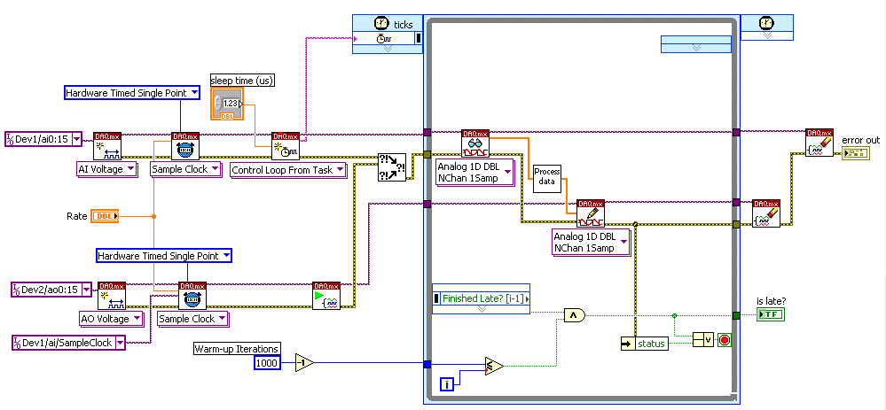
- Create a Control Loop From Task timing source for the Timed Loop. This signal serves as the timebase that drives the execution of the Timed Loop.
- The Timed Loop provides feedback to the application as to whether the previous iteration completed in time. It does this through the "Finished Late [i-1]" node.
- Allow a few warm-up iterations to account for the effects of processor-caching and other events that may occur during the first iterations of the loop.
Sample Block Diagram

Notes
- The Analog Input Read VI is implicitly configured to polling mode when using the Control Loop From Task timing source. Polling mode avoids the additional scheduling overhead associated with interrupts inside the Timed Loop.
- You can increase the Analog Input Conversion Rate manually through DAQmx Timing properties. This reduces the total amount of time spent converting the requested number of samples. It is important to consider the minimum settling time specifications for the complete data acquisition system to avoid signal degradation and interference.
- Do not use the Wait For Next Sample Clock VI for any of these tasks.
- Lower-priority processes, including other Timed Loops with lower priorities, can execute while the Timed Loop waits until its next iteration.
- To optimize multi-channel control applications in which lower-priority threads might require additional processing time, provide a non-zero value for the sleep time (us) parameter of the Create Timing Source VI. This non-zero value allows other threads to use the time spent converting analog input samples to perform other tasks such as communication or logging to disk.
- The maximum amount of sleep time you can set without impacting the overall rate of the application depends on several factors, including the number of analog channels being acquired, the sample conversion rate, and the system's specifications.
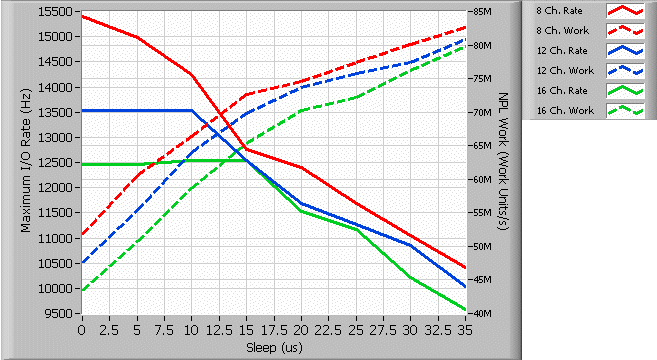
The following diagram shows, for multiple channel configurations, the effect of the amount of sleep over the maximum achievable rate and the amount of work lower-priority threads can execute at such rates.

*See benchmark configuration below.
The graph shows that, when acquiring 8 channels using a specific hardware and software configuration, the maximum achievable rate decreases as soon as the amount of sleep time increases from 0 to 5 µs. This is not, however, the case for the 12- and 16-channel configurations, for which increasing the amount of sleep up to 10 and 15 µs respectively has no visible effect on the maximum achievable I/O rates. In the 12- and 16-channel case, the additional sleep interval allows other threads to execute more work (refer to definition below) without affecting the overall I/O rate of the application.
Benchmark Configuration
Hardware Configuration:
- NI PXI-8196 RT Controller
- NI PXI-6070 E Series MIO device
- NI PXI-6723 Analog Output device
Software Configuration:
- LabVIEW Real-Time 8.0
- NI-DAQmx 8.0
- Ethernet driver set to polling mode
Benchmark details:
- A work unit is defined as the number of times a normal-priority loop can increment an unsigned 64-bit number while the I/O Timed Loop, depicted in the sample block diagram above, runs in parallel with it.
- The analog input conversion is not explicitly configured. This means that the DAQmx driver auto-calculates it based on the number of channels and desired sample clock rate.