Clocks
Periodic digital edges measure time and are called clocks. Clocks such as a sample timebase clock and the 20 MHz timebase clock mark the passing of time or are used to align other signals in time. Clocks usually do not cause actions in the sense that triggers do. The names of clocks usually do not refer to actions. The sample clock is a notable exception.
Clocks in NI-DAQmx
The following are some common clocks used by DAQ devices. Refer to your device documentation for all the clocks on your device.
- AI Convert Clock—The clock on a multiplexed device that directly causes ADC conversions. The default AI Convert Clock rate uses 10 µs of additional settling time between channels, compared to the fastest AI Convert Clock rate for the device. When the Sample Clock rate is too high to allow for 10 µs of additional settling time, the default AI Convert Clock rate uses as much settling time as is allowed by the Sample Clock rate. If there are multiple devices in the same task, the same amount of additional settling time is used for all devices in the task, even if their maximum AI Convert Clock rates differ.
- AI Convert Clock Timebase—The clock that is divided down to produce the AI convert clock.
- AI Sample Clock—The clock that controls the time interval between samples. Each time the sample clock ticks (produces a pulse), one sample per channel is acquired.
- AI Sample Clock Timebase—The clock used as the onboard clock source of the sample clock. When the source of the sample clock is set to the onboard clock, the Sample Clock Timebase is divided down to produce the sample clock. When the source of the Sample Clock Timebase is also the onboard clock, the master timebase is divided down to produce the Sample Clock Timebase.
- AO Sample Clock—The clock that controls the time interval between samples. Each time the sample clock ticks (and produces a pulse), one sample per channel is generated.
- AO Sample Clock Timebase—The onboard clock used as the source of the AO sample clock. The AO Sample Clock Timebase is divided down to produce the AO sample clock.
- Counter Timebase—The clock connected to the source terminal of a counter (Ctr0Source, for example).
- Master Timebase—An onboard clock used by other counters on the device. The master timebase is divided down to produce a slower clock or to measure elapsed time. This timebase is the onboard clock used as the source of the AI Sample Clock timebase, the AO Sample Clock timebase, and the counter timebases, for example.
- 20 MHz Timebase—The onboard clock source for the master timebase from which other timebases are derived, if the device does not support an 80 MHz Timebase. Otherwise, the clock produced by dividing the 80 MHz Timebase by 4.
- 80 MHz Timebase—The onboard clock source for the master timebase from which other timebases are derived.
- 100 kHz Timebase—The clock produced by dividing the 20 MHz Timebase by 200.
 |
Note M Series and C Series devices do not have a master timebase of an arbitrary frequency. These devices use the 20 MHz/80 MHz/100 kHz timebase directly. |
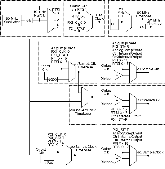
The following diagram illustrates the M Series clocks that comprise analog input and analog output timing. The black circles in the diagram represent terminals.

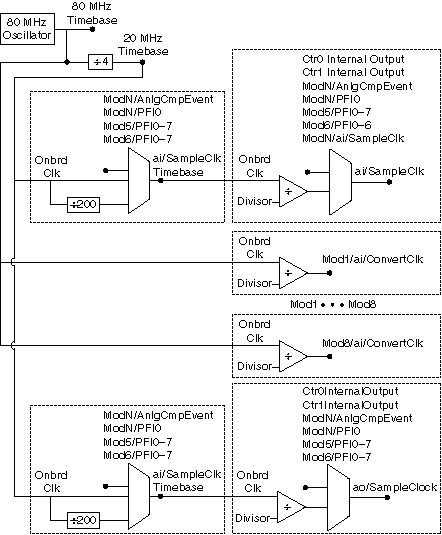
The following diagram illustrates the C Series clocks that comprise analog input and analog output timing.

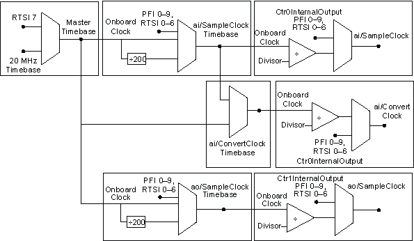
The following diagram illustrates the E Series clocks that comprise analog input and analog output timing. The black circles in the diagram represent terminals.

Trigger and Clock Distinction
The distinction between triggers and clocks is blurred when the digital edges used as a trigger are periodic. In such a case, a clock causes the device to perform an action. The sample clock is the primary example. The stimulus for the action of producing a sample is so often a clock that NI-DAQmx configures the sample clock instead of the sample trigger. The distinction is made clear when you consider the sample clock is in fact just one way of providing the source of a sample trigger.