Counter Parts in NI-DAQmx
A counter contains several advanced terminals that you can use to perform time measurements and generate pulses. For most applications, NI-DAQmx automatically makes the proper routes from the terminal connector block to the correct advanced terminal with no additional routing required. For advanced applications, you might need to make explicit routes to the internal counter terminals.
Advanced Terminals and Common Counter Applications
The following lists the names of the advanced terminals as well as their common uses:
CtrnGate—The signal at this advanced terminal is used as the Start Trigger, pause trigger, sample clock, or the input signal being measured. The following table lists how this terminal is used in various applications:
| Application | Purpose of Gate Terminal |
|---|---|
| Pulse Generation | Pause or Start Trigger |
| One Counter Time Measurements | Input Signal |
| Two Counter Time Measurements | Unused |
| Nonbuffered Edge Counting | Pause Trigger |
| Buffered Edge Counting | Sample Clock |
| Two-Edge Separation | Second Input Terminal |
| Position | Z Input Terminal |
CtrnSource—The signal at this advanced terminal is either the input terminal for the measurement or the counter timebase. The following table lists how this terminal is used in various applications:
| Application | Purpose of Source Terminal |
|---|---|
| Pulse Generation | Counter Timebase |
| One Counter Time Measurements | Counter Timebase |
| Two Counter Time Measurements | Input Terminal |
| Nonbuffered Edge Counting | Input Terminal |
| Buffered Edge Counting | Input Terminal |
| Two-Edge Separation | Counter Timebase |
| Position | A Input Terminal |
CtrnInternalOutput—The signal at this advanced terminal is where the pulsed or toggled output of the counter appears. The output of a counter pulses or toggles when the counter reaches terminal count. When counting down, the counter reaches terminal count when the count reaches zero. When counting up, the counter reaches terminal count when the counter rolls over. To configure the counter to toggle or generate pulses, use the Export Signal function/VI with Counter Output Event as the signal name.
For the output of a counter to appear at the I/O connector (Ctr0Out, for example), the signal on the internal output terminal must be routed to a terminal on the I/O connector. For pulse generations, this route is automatically made to the dedicated counter output terminal on the I/O connector. For measurements, if you are interested in observing this signal, you need to manually make this route to the appropriate pin on the I/O connector using the Export Signal function/VI with Counter Output Event as the signal name. After you route the internal output of a counter to the I/O connector, the signal remains on the I/O connector until the device is reset or you explicitly tristate the terminal.
CtrnAux (TIO-, STC II-, and STC III-Based Devices)—The following table lists how this terminal is used in various applications:
| Application | Purpose of Source Terminal |
|---|---|
| Pulse Generation | Unused |
| One Counter Time Measurements | Unused |
| Two Counter Time Measurements | Unused |
| Nonbuffered Edge Counting | Optional Count Direction Terminal |
| Buffered Edge Counting | Optional Count Direction Terminal |
| Two-Edge Separation | First Input Terminal |
| Position | B Input Terminal |
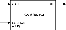
The main parts of a counter include the following:
A GATE input terminal controls when counting occurs. A GATE input is similar to a trigger because it starts or stops a count.
A SOURCE (CLK) input terminal is the timebase for a measurement or the signal to count.
A count register increments or decrements the number of edges to count. If the count register decrements, it counts down to zero. The count register size is the number of bits in the counter, and you calculate it as Count Register = 2no. of bits.
An OUT signal terminal can output a pulse or a pulse train, which is a series of pulses.
