User-Defined Data Types |
Top Previous Next |
|
User-defined data types, or structures, after configured on User Defined Types configuration window, can be used by Driver operations the same way as pre-defined data types. These data types are in fact structures whose elements may have different native data types, that is, a user-defined data type is merely a structure defined based on Driver's pre-defined data types (native or built-in data types), allowing users to configure Block Tags where each Element may have a different native data type. Users can use almost all data types pre-defined by the Driver in their structures. The only data types not allowed are Bit data types, eight-bit data types, variable-size data types, such as String and BCD, and event data types linked to specific SOE functions. Once a data type is defined, users can link it to any Tag, as long as it uses Modbus functions supporting Words, that is, it is not allowed to link a user-defined data type to an operation that defines as its reading function (Read) the 01 function, for example, because that function only reads bits. In addition to the definition of structure elements, whose values are returned in Block Elements, users can also define the type of a Tag's timestamp, as well as the default address for that structure, address that is used for the B4 parameter of Tags available using E3's Tag Browser.
ApplicationsUser-defined data types were originally implemented for use with Elipse Software's Generic SOE Reading Algorithm (Gen SOE), as this algorithm performs a reading on data structure tables. In addition to using with SOE's generic algorithm, this feature can also be used to group different data types on a single Block Tag, optimizing communication in applications without Superblocks, such as Elipse SCADA, or if the device in use for some reason does not allow using Superblocks (please check topic Superblock Reading).
Configuring User-Defined Data TypesConfiguration of user-defined data types is performed on a specific window, by clicking User Defined Types on Operations Tab of Driver's configuration window, as shown on the next figure. 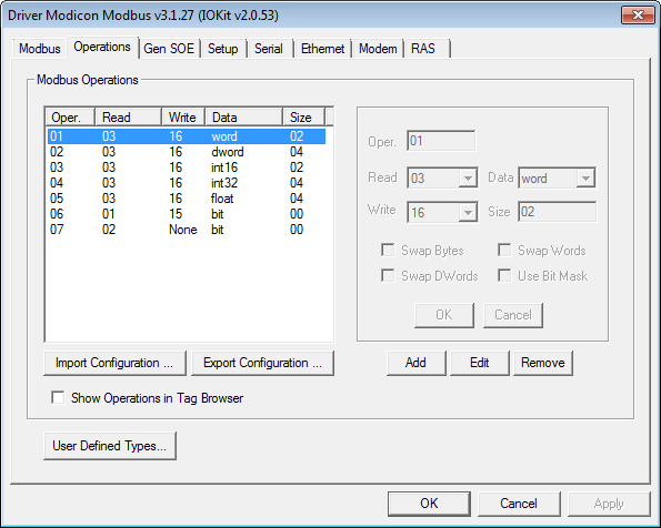 Operations tab of Driver's configuration window This window to configure user-defined data types allows editing files with structure configurations. When opening this window for the first time, it displays the default configuration file (with comments), which defines three example types that appear commented with multiple-line comments ("/*" and "*/"), as explained later. The next figure displays the configuration window for user-defined data types, with a small file defining these three example data types. 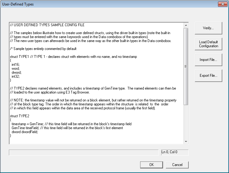 Configuration of user-defined data types Notice that line comments always start with "//", identifying what is on the right, on the same line, as a comment, following the pattern for line comments of the C++ programming language, which is also used for other languages such as Java and C#. Comments with multiple lines are also supported, still following the same C++ syntax, starting by "/*" and finishing by "*/". Notice that the example file that accompanies this Driver already applies that comment format to its example types, leaving them commented by default. Remove the lines indicated by "/* Sample types entirely commented by default" and "*/" (without quotation marks) so that all three example data types are ready to use. As the text of the configuration file changes, the status bar displays the result of this file's syntactical analysis, in real-time. This status bar displays a "Status: OK!" message if no errors are detected in this file. The line and column of cursor position in the edit box are always displayed on the right side of the status bar. Errors displayed on the status bar always reference the line and column number where it was detected. This check can be also fully performed by clicking Verify and, in case of any error, cursor is then automatically placed on the error line. The definition of each type has the following syntax (elements inside brackets are optional): struct <Type Name>
{
Where: ·struct: Keyword, lower case, starting the definition of a user-defined data type. ·<Type Name>: Name by which this new data type is identified by the Driver. This is the name displayed on the combo box Data, when configuring operations. Its maximum size is six characters ·timestamp: Optional field indicating that this structure contains a device-defined timestamp, which must be returned in Tag's Timestamp field. Each structure can have only one timestamp. The order in which it appears on this structure affects the position in which this field is read in the frame returned by a device (notice that in Tags this value is returned only in the Timestamp field). Any date and time data types supported by this Driver can be defined. In the current version, this Driver supports date and time data types GenTime, Sp_time, UTC64d, and UTC32. For more information about data types, please check topic Supported Data Types ·DefaultAddress: Optional field specifying a default address value, used to fill the B4 parameter of Tags in Tag Browser referencing operations containing this structure. Address values can be provided in decimal or hexadecimal format. To use the later format, users must precede the number with the "0x" prefix (for example, using "0x10" to encode the decimal value 16 to hexadecimal) ·<date and time type>: Pre-defined date and time data types for this Driver, which can be used as a timestamp by a slave device. In the current version of this Driver, native data types GenTime, Sp_time, UTC32, and UTC64d are accepted ·<type>: Element's data type. It must be defined as one of Driver's pre-defined data types, and written as it appears on the combo box Data, on the configuration window for operation parameters, respecting lower and upper case. Bit data types, eight-bit data types, and variable-size data types, such as BCD and String, are not allowed ·[name of element]: Optional parameter defining a name for each Block Element. If defined, determines a name for Block Elements in Tags displayed in E3's Tag Browser. If not defined in structure's declaration, this Driver then sets default names to Elements in Tag Browser, with the keyword "Element" followed by the index of that Element in the Block ("Element1", "Element2", etc.)
Importing and ExportingThe Import File and Export File options allow importing and exporting a configuration file with user-defined data types to text files on disk. These options can be used to create backup copies of a file, or to share it among several Drivers. This file is always saved and read using Windows default ANSI format (Windows-1252 Charset). Future versions of this Driver may include support for other formats. In addition to copying a file to disk, users can also use shortcut keys CTRL + A (Select All), CTRL + C (Copy), and CTRL + V (Paste) to copy and paste this file's content to another Text Editor. The Load Default Configuration option loads the default configuration file again in the editor, the same file loaded when the configuration window is opened for the first time.
Using User-Defined Data Types with Tags Configured using StringsNames for user-defined data types can be used as mnemonics for the Type field in the Item parameter, such as with Driver's native data types, as long as this name has been previously declared, as defined earlier in this topic.
For more information on Tag configuration using Strings, please check topic String Configuration. Example: 1.Read or write Holding Registers (functions 03 and 06) of address 100 from a device with Id 5, interpreted as a user-defined data type named "mytype", with Slave Id in the Item field: a.Device: "" (empty String) b.Item: "5:shr100.mytype"
Using User-Defined Data Types on Numerical ConfigurationAfter defining new data types in the configuration file on the User-Defined Types window, these data types are available for use in Driver operations. Remember that only operations that use Modbus functions for access to 16-bit registers, such as functions 03, 04, 06, and 16, allow user-defined data types. The next figure displays the configuration of a new operation that uses a user-defined data type (structure) named TYPE3, showed on the previous example, after clicking Add. 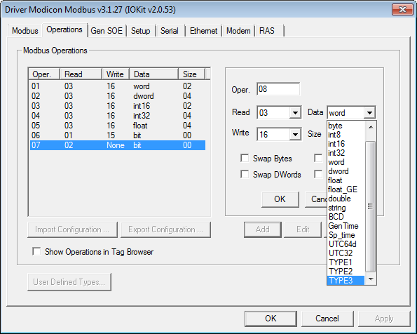 Adding a user-defined data type
After defining a new operation, by using the new type TYPE3, define a Block Tag with that same data type and size equal to the number of elements of that structure, as shown on the next figure. 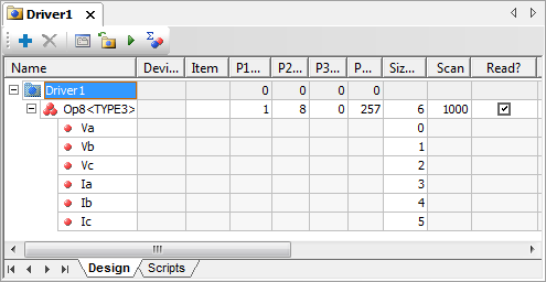 Declaring Tags using structures in E3 or Elipse Power If a name was defined for each element of this structure, then users can use E3's Tag Browser to include a Block Tag referring the desired data type in an application, without typing it again. To use this feature, users must select the Show Operations in Tag Browser option on Operations tab. The next figure shows how to perform this procedure. 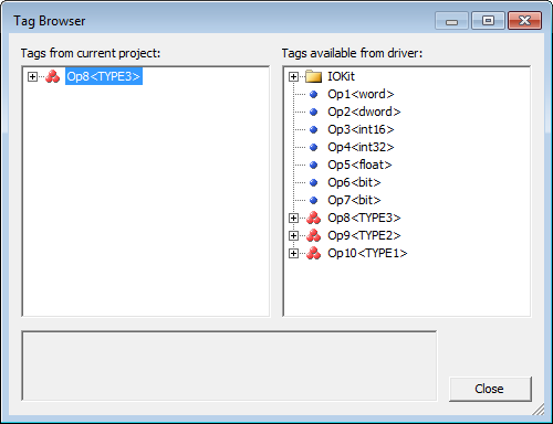 Using Tag Browser to define Tags using structures As this figure suggests, click
Event-Reported ReadingUser-defined data types or structures are generally used to define events in PLC's memory, and can be used with Elipse Software's Generic SOE Reading Algorithm. However, if users want to read events organized in PLC's memory, such as a sequence of structures, in an operation that only uses protocol's public reading function, that is, without using special functions with the SOE algorithm, such procedure can be performed in two ways: ·Block Reading: Create a Block with a number of Elements that is a multiple of the number of elements of user's data structure. For example, a user-defined data type or structure with two elements that represent events collected on an arrangement in PLC's memory. If users want to read a block with five events, they must define a Block Tag with 10 Elements. Thus, a single reading from this Tag retrieves all events at once ·Event-Reported Reading: Uses a sequence of Tag's OnRead events to read a data block. With it, considering the example on the previous item, instead of creating a Tag with 10 Elements, users only need to create a single Block Tag with two Elements, configuring its B3 parameter as "5". This way, when performing a Tag reading, E3 calls Tag's OnRead event five times, and at each call the Elements and properties of this Block Tag contain data related to a specific event. The most common usage for Tags reported by events is storing events read directly from a historical database. This is easily performed using Historic's WriteRecord method previously linked to this Tag, on the OnRead event of the event-reported Tag. For more information, please check topic about Event-Reported Tags on E3 User's Manual
In other words, every I/O Tag using structures and using a protocol's public reading function (this resource does not work for special SOE functions), becomes an Event-Reported Tag if its B3 parameter is configured with a non-null value. In case of special SOE functions, such as the Gen SOE function, the event-reported return is defined by the function's proprietary algorithm itself. For more information about I/O Tag configurations, please check topic Configuring an I/O Tag.
|