Operations Tab |
Top Previous Next |
|
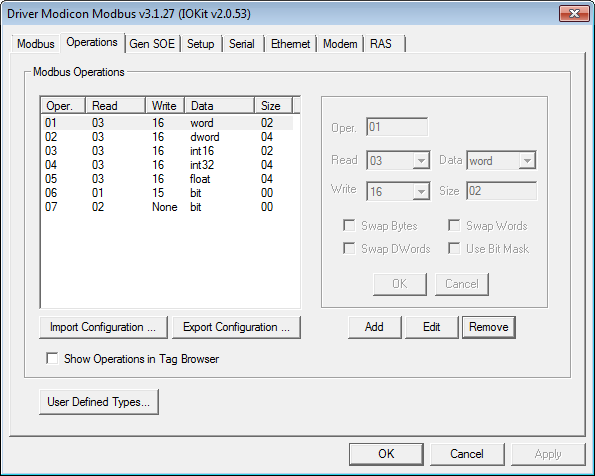
This topic describes how to configure the Operations tab on Driver's configuration window, where all operations used on I/O Tags are defined, as shown on the next figure. Configuring operations is no longer used when configuring Tags by Strings, it is only used in the old numerical configuration (N/B parameters) on Elipse SCADA.  Operations tab on Driver's configuration window OperationsFor a proper usage of this Driver, users must define which reading and writing Modbus functions are used for each I/O Tag. To do so, if Tag configuration is performed using the old N/B numerical parameters in Elipse SCADA, select the Operations tab on configuration window. For this Driver, Operations are configurations defining how each I/O Tag performs data writings and readings to and from a device. An operation is nothing more than a definition of a pair of protocol functions, one for writing and another one for reading, and a specification for additional conversions on the format of data that can be linked to application Tags. In other words, in Modbus Driver the N or B numerical parameters of I/O Tags do not directly reference protocol functions, but rather pre-configured operations, which by their turn not only inform functions (protocol's native or even special ones) to use when communicating, as well as the way native protocol data must be interpreted. Configuration of I/O Tag parameters is described later on topic Configuring an I/O Tag. Next, there is a description of the configuration of operations, which must be later linked to each I/O Tag.
FunctionsThe Modbus protocol defines reading and writing functions, which can access distinct address spaces on a device, and with specific data types. Functions 03 and 16, for example, protocol's most used ones, are responsible for reading and writing Holding Registers, which are simply 16-bit unsigned integer values (Words). Modbus protocol's default functions provide data only in basic 16-bit Bit and Word formats. There are no additional data formats in protocol's specification. A list of all Modbus functions supported by this Driver, which can be set to the configured operations, can be checked on topic Supported Functions. In addition to protocol functions, this Driver also contains some Special Functions that are not part of protocol's standard, with a proprietary format and commonly used for reading events (SOE).
Data FormattingIn addition to allow linking functions (from the protocol or special ones) to specific Tags, operations also allow defining an additional formatting to apply to data, providing support to additional data types, not specified by the protocol, such as 32-bit (Float) and 64-bit (Double) floating point values. Supported data types are described on topic Supported Data Types. It is important to notice that, when 32- and 64-bit data types are defined in operations, users must define protocol functions that work with 16-bit registers. This way, reading data with more than 16 bits results in reading several 16-bit Modbus registers from a device, that is, to read a Tag linked to an operation defining a 32-bit Float data type, this Driver must read two consecutive 16-bit registers from a device, concatenate them, and then perform a conversion to a Float format. Users can also define eight-bit data types (Byte, Int8, or Char) in operations. Notice that, as protocol functions do not allow reading and writing isolated bytes, for each two Block Elements of eight-bit types, this Driver is forced to access a distinct 16-bit register on a device. For that reason, this Driver does not allow writing eight-bit data types to Tags, to isolated Block Elements, or to Blocks with odd or unitary sizes. Writing eight-bit data types must be always performed even-size Blocks.
User-Defined Data TypesIn addition to pre-defined data types (native or built-in data types) described on topic Supported Data Types, this Driver also allows user-defined data types. These data types must be declared on a specific window, by clicking User Defined Types, at the bottom of Operations tab. Such data types are structures created from pre-defined data types. For more information about user-defined data types, please check topic User-Defined Data Types.
Byte OrderIn addition to protocol's reading and writing functions and the data type used, each operation also allows setting additional manipulations to bytes, related to a byte order, that is, the order of bytes inside every value. These are called swap options (Swap Bytes, Swap Words, and Swap DWords). Such options only need to be enabled for devices that do not respect protocol's default byte order. The Modbus protocol defines that its 16-bit values always use a byte order known as big endian, also known as Motorola, because it is used by this manufacturer. The big endian standard always defines a byte order so that the most significant byte of each value comes first. Thus, as an example, when reading the hexadecimal value 1234h, the device first sends the most significant byte 12h and then the least significant one, 34h. For devices that do not implement protocol's default byte order, and use another one known as little endian or Intel, data is sent with the least significant bytes first. Users must then enable those swap options to reverse that byte order. There are also devices that use different byte orders for 32- and 16-bit types. For devices that, for example, use Modbus' default byte order (big endian) for 16-bit types, but provide 32-bit data with the least significant Word first (little endian), users must only enable the Swap Words option, leaving the Swap Bytes option deselected. There are basically three possible situations: ·For devices that provide data using Modbus' default byte order (Motorola or big endian), with the most significant bytes first, users must left all swap options disabled. This is the most common situation ·For devices using another byte order standard, with the least significant bytes first (little endian), users must enable all swap options referring to the data type used, that is, for 16-bit types, enable the Swap Bytes option. For 32-bit data types, enable the Swap Bytes and Swap Words options. For 64-bit types, all three swap options must be enabled ·In the least common case, devices that use different byte orders for different data sizes, providing, for example, the most significant byte of each Word first, but the least significant Word of each DWord first, then users must evaluate in which case each swap option must be enabled, so that it converts a value returned by a device to protocol's default big endian format
To check if a device uses some unusual byte order format, check its manufacturer's documentation. In case this information is not found on that documentation, please contact manufacturer's technical support. The topic Frequently Asked Questions contains tips on byte order configurations for some devices that are known to use swap options.
Bit MaskThe Use Bit Mask option is an advanced feature, used in specific and unusual cases where users want to read only a bit from the value returned by a device, but they cannot use application's bit mapping. For most users, application's bit mapping fields are the best alternative to access bit masks, and there is no need to use this Driver's feature. This feature was initially created to allow reading bits from Holding Registers by specialized E3 libraries, in situations that prevented the usage of application's bit mapping. In this case, this Driver reads a value from a device normally and then masks it, to return to Tag's Value field only the specified bit (0 or 1). The definition of a bit number to return is performed on I/O Tag's N3/B3 parameter. The Use Bit Mask option can only be used with integer data types with 16 bits or more (Int16, Int32, Word, or DWord). In addition, operations that enable this option can only be used for reading. The Modbus function for writing operations (Write) that use this mask option can be defined as None.
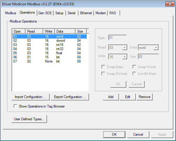
Driver's Default OperationsBy default, when a new Driver is added to an application, this Driver is already created with seven default operations, described on the next table. Default operations
These operations are the most commonly used, and operation 1 is the most common one. For most devices, select all operations needed among the ones provided by default, there is no need to create new operations or change the configuration of these default operations.
Defining New OperationsTo add a new operation to a Driver, click Add.  Adding a new operation To configure this new operation, select a number for it (this number is used on I/O Tag's N2/B2 parameter), which function to use for reading, and which function to use for writing, as well as informing a data type to be read or written by this Driver. Notice that, when clicking Add, this Driver already suggests a value that is not in use for this new operation. For more information about supported data types, please check topic Supported Data Types. All other fields can be configured as needed. The next table contains a description of these fields. Field options for operations
Protocol functions that can be configured in operations' Read and Write fields are described on topic Supported Functions. The next table describes each one of the available options. Available options on Operations tab
|