Acquisition Procedure in an Application |
Top Previous Next |
|
This topic contains a detailed explanation on the configuration of an application to acquire events accumulated in a PLC or programmable slave device. Reading events in an application is performed using Tags that reference the special reading function Gen SOE. Tag's data type defines the structure of events stored in the device's event table. If a Driver's native data type is defined (a built-in type), each event contains only one element of this type, without a device-provided timestamp (a timestamp represents the instant events were collected). On the other hand, if user-defined data types are used, then users can define structures for events, including timestamps, as explained later on this topic. Next, there is a description of the configuration of Tags using the new methodology of configuring by Strings (Device and Item fields), as well as the old numerical configuration used by Elipse SCADA (N and B parameters).
String Configuration·Device: "<Slave Id>:" ·Item: "elsoe<N>.<start add.>[.<type>[<type size>]][.<byte order>][/bit]"
Where: ·N: "<Slave Id>:" ·start add.: Address of the first control register, using the value defined on the example table of topic Event Table ·type: Native or user-defined data type used for each event (please check topic String Configuration) ·type size: Used only for variable-size data types (please check topic String Configuration) ·byte order: Byte ordering. It can be omitted for devices fully compliant with protocol's standard (please check the Byte Order item on topic String Configuration for more information). When structures are used, it only affects their individual elements (please check topic User-Defined Data Types) ·bit: Bit masking. Usually can be omitted, it would hardly be used here (please check the Bit field on topic String Configuration)
Example: ·Device: "1:" ·Item: "elsoe150.&h101.TYPE3"
The TYPE3 data type is defined as follows in Driver's default example file (please check topic User-Defined Data Types). // This type has an UTC32-type timestamp
// and a few named elements
This is a Structure data type containing six data fields and a timestamp. Therefore, this Tag must be a Block with six Elements to represent that structure. Notice that, as already explained, timestamp's value, although it occupies registers in the PLC, does not need Block Tag Elements, because its value is returned in Tag's timestamp field.
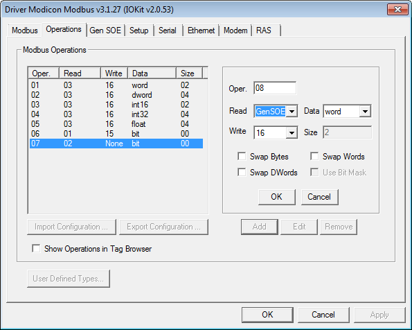
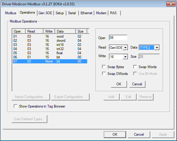
Numerical Configuration (N and B Parameters)To configure Tags for reading Elipse SOE using a numerical configuration, users must configure an operation on Operations tab, using the special function GenSOE. The next figure shows an example of a new operation added using special function GenSOE with a Word data type.  Special function GenSOE Notice that function 16 (Write Multiple Registers) was selected as its writing function, which is the most commonly used function. However, users are encouraged to use function 06 (Write Single Register) whenever supported by a device. The next figure shows the same operation with a user-defined data type TYPE3 (please check topic User-Defined Data Types), which is a data type defined in the example default configuration file, available with this Driver when it is firstly added to the application, used as an example in this topic.  Configuration using the GenSOE function and a user-defined data type Data type TYPE3 is defined in Driver's example file as follows: // This type has an UTC32-type timestamp
This is, therefore, a Structure data type with six data fields, a timestamp, and a default address (Tag's B4 parameter) equal to "101H" (257 in decimal). To read it, users must define a Communication Block Tag with six Elements and the following configuration: ·B1: Slave device's address (PLC) on the network (Slave Id) ·B2: 8 (a previously defined operation with special function Gen SOE) ·B3: N (size of a device's table, as the maximum number of events that table can contain) ·B4: 100 (address of the first control register, using a value defined on the example table of topic Event Table) ·Size: 6
Notice that, if E3's Tag Browser is used to insert a Tag in an application, as explained on topic User-Defined Data Types, Tag Elements are already named according to the name given to structure elements when they were declared. Tag Browser can be opened by clicking
UsageOnce defined an appropriate Tag (or Tags), enable its scan and let the Driver collect events from their respective table, whenever new events are detected. Tags linked to the GenSOE function (elsoe when configuring by Strings) are always event-reported. This means, as already explained on topic User-Defined Data Types, that this Driver can return several events on a single reading operation, that is, on a single interval of a Tag's scan. This means that this Driver returns a set of events (for the previous example, sets of blocks with six data fields and a timestamp) at once, which produces a sequence of OnRead events on a Tag, one for each event (a block with six data fields and a timestamp) returned by this Driver. For detailed instructions on the right way to handle event-reported Tags, please check topic Tags Reported by Events on E3 User's Manual. Elipse SCADA User's Manual also contains an analogous topic. In short, the usual way of handling event-reported Tags is by adding a call to the WriteRecord method of a previously linked Historic object on Tag's OnRead event, ensuring that all events reaching this Historic are registered. In this case, this Historic must be configured without a dead band (the DeadBand property set to zero) and disabling historic by scan (in E3, the ScanTime property set to zero). Tag's EnableDeadBand property must also be configured to False.
Optimization and CompatibilitySome devices, such as PLCs by ATOS, do not support block readings using data types with different structures. In practice, this prevents a Driver to read data from control and event registers as a single block. To collect PLC events with these restrictions, users must disable the Enable Control and Data Registers Grouping option on Gen SOE tab. |